
(This is one of a pair of unrelated Tiny projects that seem to be going on in parallel. I don’t think I could have chosen two more confusable projects if I’d tried.)
These are the first steps in implementing a little I2C (oops, Two-Wire Interface) network with simple, cheap Tiny85 nodes for automating a dollhouse. This is all from scratch, and in small steps – since I don’t really know if it will work. (Update: it works. I really should distill a nice post from this cron history.)
The vision is a dollhouse wired with 4 conductor cable – +5, Gnd, and 2 for a TWI network – so little slave nodes can be installed where ever inputs or “actuators” are desired. An Arduino is the bus master and logic host for the system. Open a door and a switch on a slave notices. Maybe that causes the audio slave to play a creaky door noise, or maybe it turns the fireplace on, or maybe it only turns the fireplace on if the slave with the photo sensor has noticed it’s dark out. And if something in the house just needs (5V) power, the cabling has that covered as well. Should be pretty powerful.
Tiny85 slave node
At ~$1.30 each for about five I/O lines, Tiny85s are about perfect for the slave nodes. The power+network connection is a bit of ribbon cable and a 4 pin 0.1″ male header. The DH is to be wired with a bunch of 4 pin females. Power and ground are on 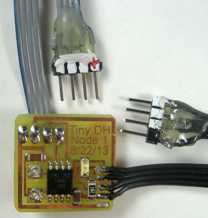 adjacent pins 1 and 2, so if you plug the unpolarized plugs in backwards there should be no damage.
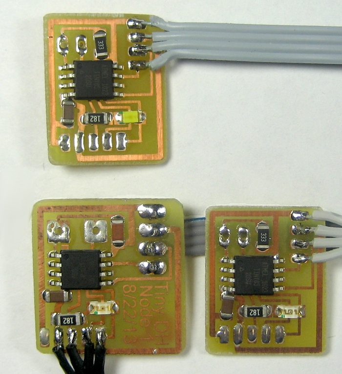
Here’s the very first prototype slave node. Nothing there but the Tiny, an LED (and resistor), a pullup for Reset, and a small cap across the supply pins, plus the power/network connection and pads for the three I/O pins to connect to the slave’s target inputs/outputs. No crystal – the internal 8MHz oscillator should be fine.
To save space, I omitted the ICSP header by taking advantage of the fact that the “network” cable already had 4 of the 6 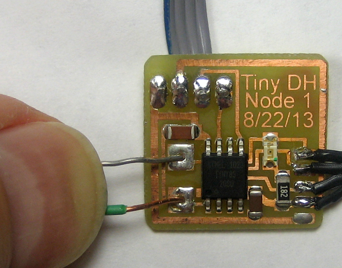 needed pins. I added two pads for the other lines needed for programming, figuring I’d just hold the extra two wires in place for the 10 seconds needed to program the node. Holding the wires down let me download a Blink sketch first try. It works! A little more fiddling let me run avrdude in interactive (-t) mode and set LFUSE to 0xE2 instead of 0x62 to let it run at 8MHz instead of the factor default of 1MHz.
I brought out 5 pads for the I/O, including +5 and Gnd. For the first tests, I figured I didn’t need +5, so I just used 4 pads. Confusion #1 struck: I was going to have two identical ribbon cables coming out with identical 4 pin connectors. Bad idea. Fortunately, I had some black ribbon cable, so that visual difference will probably save me from doing something dumb. One mine sidestepped.
Too many N-wire interfaces
To keep me on my toes, this project – and a Tiny84 sister that happens to be underway at the same time – use all three of the simple few-wire serial interfaces. For programming, both use SPI (with its Gnd, MOSI, MISO, SCK), as do most all the AVR chips. The dollhouse network is I2C (with its Gnd, SDA and SCL). Of course, since Philips has imposed licensing costs for “I2C”, many implementations sidestep the licensing by calling it the “Two Wire Interface”, or TWI. And the Tiny84 datalogger in development at the same time as this also uses the “1-Wire” interface Dallas (now Maxim) introduced, with its Gnd and data/power lines. The 1-wire slave device may extract “parasitic power” from the mostly-high data line with its pullup resistor, making it possible to connect a slave with only 2 wires.
The AVR ATmega chips – like the classic Arduino ATmega328P – have special hardware in the chip to directly support I2C/TWI. The “Wire” and “TWI” libraries that ship with Arduino distributions are written to use that hardware. That’s in addition to the also built-in hardware to support SPI, used for programming. The Arduino distribution also includes a library to talk to other SPI devices. We’ve come to take for granted that Arduino can talk to most any devices with those protocols with no problems.
But to add to the fun, while the Tiny family chips do support SPI in hardware (they have to be programmed, after all), they don’t have the same I2C/TWI support hardware on chip, so the standard Arduino libs can’t work. Tinys do, however, have hardware support for the simpler Universal Serial Interface – USI. That hardware can also be convinced to do most of the work for I2C/TWI – though not all. Fortunately, the open source community has written (several!) libraries to (ab)use the USI hardware in Tinys to support I2C/TWI. There’s a USIi2c lib (gotta keep all them letters straight!) available on the Arduino site, as well as others in various github projects. Of course the library names are different, so code that works fine with the “real” Wire/TWI libs must be modified to use the Tiny libs.
Oops # 1
Because there are limited pins (especially on Tinys!), each pin can perform any of several functions: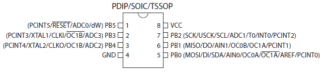 Trying to be careful and clever, I noticed pin 5 was used for both SPI MOSI and TWI (USI) SDA, and 7 was both SPI SCK and TWI SCL. If I brought those 2 out along with +5 and Gnd to make up the 4 wire power/network connection, I’d have 4 of the 6 wires for the SPI programming interface right there on a nice 4 pin connector! I’d just have to cope with separate pads for MISO and RST when I wanted to program the Tiny. Sold.
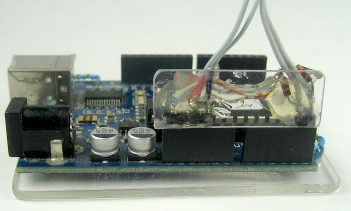
But even more cleverness (not): MOSI and SCK and +5 and Gnd were already brought out on the Arduino’s often overlooked ICSP header. I could just make up a ribbon cable with a 2×3 pin connector for that header and a 4 pin female with those 4 wires laid out in the same order as the DH “network” connector and I’d have the pigtail I needed for the bus master Arduino to talk to the slaves. For the first prototype, I could just plug them together. For larger prototypes, I could make a “hub” with one 4 pin male and a few females all in parallel that I could also plug into that same pigtail. Great!
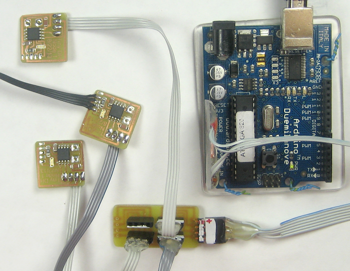
 I marked one side of the slave’s and master’s connectors with whiteout to make it easier to plug them together correctly. Here it all is, as plugged together for the very first actual TWI network test. Unfortunately, it didn’t work. A little head scratching later it hit me: The I2C/TWI interface on the Arduino is on A4 and A5, not the MOSI and SCK on the ICSP header. The whole (not so) clever approach of using the ICSP header was just wrong. I’d completely confused the SPI and I2C interfaces. Rats.
 So I took off the 6 pin female and wired the 4 relevant wires to two 2-pin 0.1″ males (for +5/Gnd and A4/A5). If I’d been thinking straight, I could have used a 4 wire ribbon in the first place. Hmpf. But just before gluing them to a piece of plastic so they just fit the right holes, I realized I’d forgotten the pullups! Added a small 3.3K resistor from each I2C line to +5, glued it all up and tried again. It works! I can now officially talk from an Arduino master to the first Tiny85 slave. (Yeah, yeah – that connector’s really ugly. But it works.)
Initial software
Ignoring various missteps involving further confusing the serial interfaces and trying to find libs that work on Tiny 84 instead of Tiny 85, here’s what I ended up with. There are two parts to the puzzle so far: an I2C/TWI implementation for Tiny85, and some master and slave sketches that talk to each other using the TWI lib(s).
AlphaNerd put a nice TinyWire package on github marked as his changes to BroHogan’s USIi2c libraries. It includes a slave sketch attiny85_i2c_slave that provides four read/write “registers” (0-3), initialized with the classic 0xDE, 0xAD, 0xBE, 0xEF. As is the custom with I2C devices, it maintains a “current register” pointer that automatically increments after each read, so a series of reads walks through the registers (and wraps). Writing to the slave alters the contents of the addressed register. I hacked it a little so if you write to non-existent register 5, the value written is used for an AnalogWrite() to the output pin the slave’s LED is on. (That pin was cleverly chosen as one that supports PWM.) Makes for an easy visual check that I can talk to the slave.
AlphaNerd’s package also contains a very useful master tool, i2crepl, which includes a scan through all 0x7F addresses on the bus, showing which addresses have devices that responded. Using a simple language with ‘[‘ as an I2C Start and ‘]’ as a Stop, you can manually enter most any read or write command you choose, and the sketch will attempt to send it on the bus. Each byte it tries to send is echoed, along with the return status from the lib trying to send it (and of course any bytes read from the slave). Obviously this requires some understanding of I2C protocol, but that’s not very complex. The tool is hugely valuable in the early steps of setting up and troubleshooting an I2C bus – which is exactly where I am. Thanks, AlphaNerd!
The I2C/TWI implementation I seem to be using on the master is rambo’s I2C package on github, based on Wayne Truchsess’s work. I think it was somehow claimed to be better than the standard Wire/TWI lib. Rambo’s package also includes an i2crepl sketch, which is probably related to AlphaNerd’s. There’s a lot of cross pollination here, and I’ve mostly given up trying to keep all it straight.
It looks like there’s a USIi2c based Tiny TWI implementation in AlphaNerd’s package as well. The slave sketch includes “TinyWireS”. That seems to be what I’m using.
There are a LOT of libraries I’ve tried or planned to try in my Arduino download directory. I remember being frustrated because some package had a TinyWireS (slave) lib, but no TinyWireM. I did finally find a package with both, but by that time I had realized it didn’t matter, since my master was on a real Arduino, not a Tiny. Part of why I’m recording all this is that I never want to have to go through it again. Part is probably just whining about how much it makes my head hurt.
It’s a network!
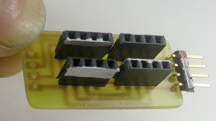 Encouraged by the ability to talk to the first slave, I populated 2 more slave boards (as one reflow job) and made up a “hub” to connect them. The hub is just some 4 pin females all in parallel – like the DH will be wired with. I marked the “white” side of all the connectors. This one has a 4 pin male as its “input” connector from the master, and has 4 more pads that will allow expanding it by daisy chaining it to another hub. I’m not sure yet how the wiring in a real DH will be implemented.
 I burned the same slave code – obviously with different addresses – in each of the two new slaves. Of course I had to do the drill of holding the other two ICSP wires down for each one to program it. Although the new nodes don’t have pigtails to talk to the outside world yet, I used the i2crepl master tool to verify that I could read and write to each of them. It’s officially a network!
 Update 9/3/13: I made up two more slaves with my last two SMT Tiny85s. I also laid out the board to be a little smaller. Here they are with one of the originals. I loaded the attiny85_i2c_slave sketch in both – with unique addresses, of course. Since there are now more slaves than fit in the hub, I made another hub, too. That plus some phone wire will give me a chance to see how it works over a much longer run.
One big surprise with these as well as the second and third slaves is that they ran fine with the fuses still set for 1MHz. (8MHz internal oscillator, div by 8 on.) I’ll run avrdude and change them to 8MHz, but I’m surprised they even ran.
 We have colors! Here’s a slave with one WS2812 RGB LED. (Thanks, Bill!) The Adafruit lib coexists happily with the USI TWI slave lib, and I can talk to this node from the i2crepl tool. Values 1-255 written to now standard register 5 walk around the color wheel; value 0 turns the LED off. I had to make up a little breakout to connect wires to the LED first, but thankfully that’s pretty easy now.
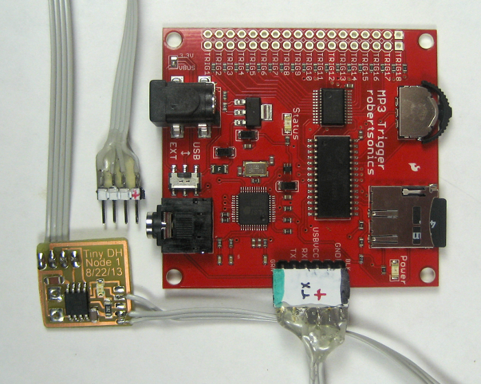 And we have sound! Here’s a slave that talks to a SparkFun MP3 Trigger board I happened to have from another project. In addition to the 18 dedicated trigger pins, the board accepts normal TTL serial in to control most everything, and even has holes laid out for the standard 6 pin connector from an FTDI cable. The cable here is just +5, Gnd, and Tx from Tiny SerialDebug. Default on the board is 38400, but since it’s not running a crystal oscillator, I opted for a more conservative 9600, taking advantage of the convenient feature of a MP3TRIGR.INI text file on the micro SD card. I dropped several sound effect clips on the card, so it’s pretty much ready to go. At $50, this board is pretty pricey for a dollhouse. I just ordered a cheaper programmable player, so I’ll try to integrate that when it comes.
As has become the custom, writing a value to register 5 plays the track with that prefix number. The network is coming along!
The bad news is that I fried one of the slaves. While trying to program it, I plugged its 4 pin connector into the programming breadboard off by one pin. (Never use a black breadboard!) The Tiny is clearly not completely dead, as it still blinks the LED with code in setup(). But apparently at least one of the pins needed to program it is blown. It won’t respond either to the programmer or to avrdude. Down to 4 slaves. 🙁 But that’s still enough for a good demo. 🙂
Getting a servo to work has been harder. The standard Servo lib uses a 16 bit timer – which the Tiny85 doesn’t have. I have a lib directory called TinyServo, but as far as I can tell it’s just the standard stuff (and doesn’t work on a Tiny). I tried SoftwareServo, but it didn’t work very well. Unfortunately, it requires calling SoftwareServo::refresh() very frequently in the main loop. But the Tiny TWI stuff also requires calling one of its functions in a tight loop in the main loop. I didn’t try removing the TWI call, but the servo just kept oscillating.
I finally just wrote my own pulse width code, calling the TWI call while waiting for the hi and lo pulse durations. Fortunately, micros() seems to work on the Tiny85. There’s almost no traffic on the network yet, so I don’t know whether my approach will work when the master is banging polls out about as fast as it can. Anyway, it’s a start.
I didn’t wire up a servo header like I did with the WS2812 and the SparkFun serial cable, figuring I’d just just use the slave with that nice black ribbon that brought out all the I/O pins. I’d gotten all the way down to wiring a servo header on the breadboard when I realized I’d decided not to bring +5 out on that cable. Grumble, grumble… So I pulled out my trusty 5V battery and used that to power the servo.
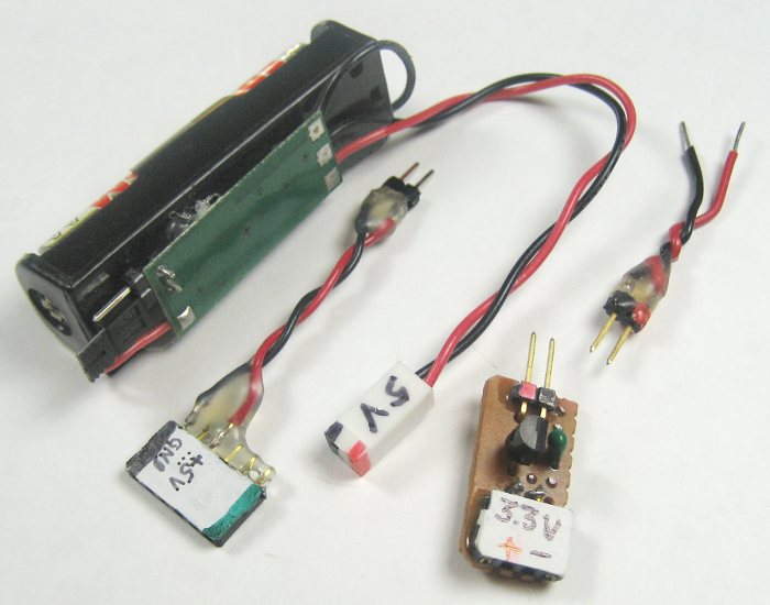 Of course there is no such thing as a 5V battery, but I got a little boost converter from SparkFun years ago that gives 5V from one AA. It was kind of pricey – 10 bucks? – but I use it all the time. It’s posing here with some friends.
Update from ~9/4/13: Fireplace LEDs “LED flickering candles”are available from lots of places. I found just the LEDs at Lighthouse LEDs and ordered some. The chip embedded in the 5mm LED runs from 3-6V without a resistor (despite what the web site says).
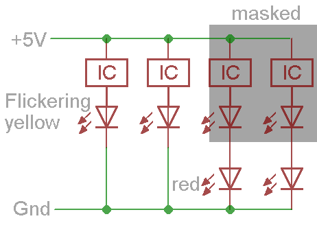 But one flickering yellow LED is kind of boring. Multiple LEDs, flickering asynchronously would be better. And it would be nice if there were some red ones, too. Gee – the current thru a flickering yellow must flicker, too. What if there was a red one in series with it?
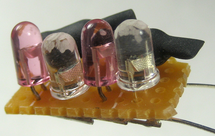 By masking the yellows that were just being used as current modulators with some heat shrink, their reds flicker all by themselves. The 5V supply in the DH should be enough for the forward drop of 2 LEDs in series. I tried it with 2 of each color, and it worked out really well. The yellow LEDs (clear packages) had pretty tightly focused lenses, so I hit the tops with a Dremel cutoff wheel to diffuse the light a little more. That helped, but there’s still a circular artifact. I think grinding the sides down would fix that, but didn’t bother on this one.
It’s now embedded in a fireplace in the DH. Some nice printed flames on clear plastic from from the castle props makes it even nicer. This one was a real win. I should get a little video clip of it.
Update 9/6/13: A Tiny84 slave? We may need quite a few photosensors for the dollhouse. Since I/O is really limited on Tiny85, and it looks like the Tiny84 with its 14 pins has 8 analog inputs, I wanted to see if I could get 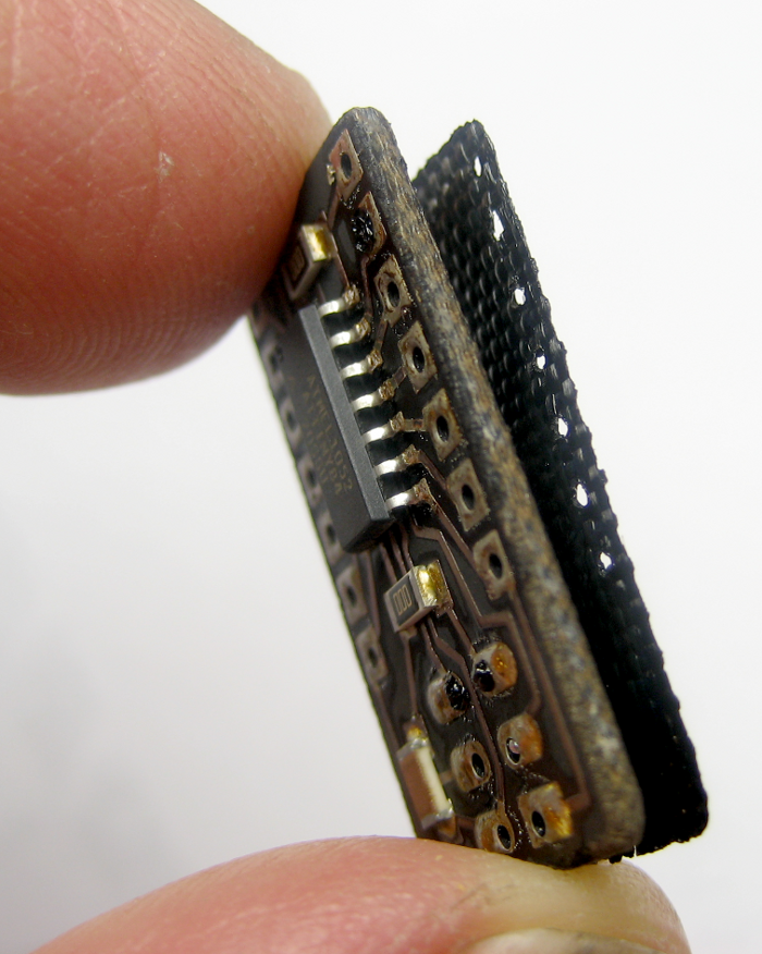 an ’84 on the I2C network. I made up a little ’84 breakout with 0.1″ header spacing so I could stick it on a breadboard and play with it.
Unfortunately, I walked away from the reflow hotplate for too long and the board got really cooked. 🙁 The controller even beeps when it’s time to turn power off and again (2 beeps) when it’s about reflow temp so it warns me to take the PCB off (if I can hear it!). On the good side, I’ll probably never walk out of the room during a reflow again!
A little later… Wow. Just on the off chance the chip wasn’t really roasted, I put the 6 pin ICSP header in and ran avrdude. It responded!
OK – next step. I peeled off the bottom delaminated layer of the board, poked the blackened material out of the holes, scraped and fluxed the pads, and put the two 7 pin headers in. Would I actually be so lucky as to have it work?
 Well, no. When I tried to plug the module into a breadboard, it didn’t fit. Apparently when I laid the board out I failed to make sure the two rows of 0.1″ headers were in fact a multiple of 0.1″ apart so they’d fit in a breadboard. Measuring in Eagle, the rows were 0.449″ apart. Rats. So close.
 But then there’s always cheating. There are no rules about how far apart two breadboards can be! I wrote a little one-at-a-time blink code and stuck a couple of the nice little 5 LED boards that are set up for pins 8-AREF on a regular Arduino. Not perfect, but that put LEDs on about 8 of the pins. (And ground even lined up on one side!) After a couple of tries (even though pin1 is marked) I got them in a sensible orientation – but it didn’t work. It took a little while, but I finally realized that one of the LEDs was on the Reset pin. That was holding it to(ward) ground thru the LED and resistor, and it was enough to hold the chip in Reset. A wire from that pin to +5 fixed that (with that LED always on), and all the pins that were connected to LEDs worked! I can hardly believe it. Guess I better stop saying “Wow!” and see if I can get it on the I2C net like I wanted to do in the first place.
 A little later… I’m using up all my luck here. I used avrdude to turn off the div by 8 fuse so it’s running at 8MHz and loaded the stock attiny85_i2c_slave sketch and the ’84 came up on the network. I couldn’t find specific mapping of the Arduino analog “Ax” pins to physical ’84 pins, but making the educated guess that ADC0-ADC7 from the datasheet would be mapped to A0-A7, I tested (almost) each one with a pot to that pin, and that mapping worked. (And the pins worked for analog in!) That was all using Tiny DebugSerial to see what values I was getting.
I couldn’t try A4 (pin4, PA4, SCL) or A6 (pin7, PA6, SDA) as they were the I2C bus, but I did try referencing A7 as “(A6+1)” and it worked. I take that to mean that the mapping is there in the code somewhere. Of course I still can’t test those two pins with a slave on the network, but the pattern looks pretty clear.
I still can’t believe that blackened board works and works well enough to do meaningful testing with. And it’s very nice that the ’84 hardware is close enough to the ’85 that the I2C stuff worked without a hitch. I guess it’s worth laying out a Tiny84 slave board!
Update from ~9/10/13: Color sensor fail There was strong interest in a “monster sensor” – so a colored monster held up to a window could be recognized by its color, perhaps triggering some corny spoken line referring to the monster’s color. I tried to get the Adafruit Flora color sensor integrated into the network (but failed). Because this is already an I2C device, it won’t talk to a slave, but rather be directly on the I2C network.
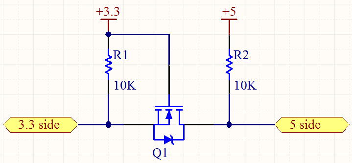 Since the TCS34725 chip the sensor is based on is a 3.3V part and the DH network is 5V, I needed level shifters as well as a 3V power source. There’s an elegant level shifter using a MOSFET and a resistor (which I still don’t understand) that looked like just what I needed. (Adafruit has another version of the sensor with a 3.3V regulator and level shifters, but the one I had was the 3V-only e-textiles version.)
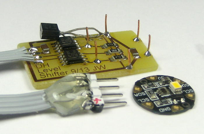 I laid out an adapter board with 2 channels of level shifter for the I2C lines plus a 3.3V regulator. The cheap MOSFETs I stock are bizzarely in an 8 pin SOIC, with 1 pin for gate, 3 for source and 4 for drain. Fine. The nice 5 pin LDO regulator I put on the board just didn’t work, and had to be replaced with a TO92. I didn’t want to clog Rachel’s color sensor thread holes up with solder, so I put some wires up that I could just tack solder to the pads next to the holes on the sensor.
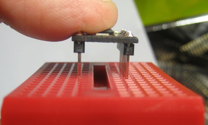
 But when I put it all together, although power and signal levels looked good, I just couldn’t talk to it from the master. Trying to simplify for troubleshooting, I wanted to run the sensor direct from an Arduino. I tacked the 4 network wires directly to the sensor for the test.
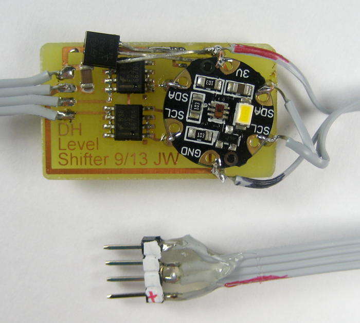
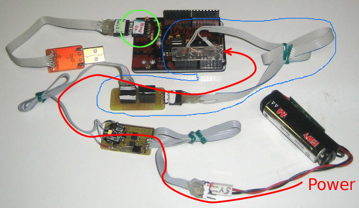 To my chagrin, I didn’t have a way to power an Arduino with 3.3V. Here’s the unholy hack I used to get 3V power to the whole system. Patching 5V into the power pins of the network connector on the color sensor adapter got 3V for the sensor. A 4 pin network cable tacked to SDA, SCL, VCC and GND on the sensor patched thru a hub (not needed – duh!) not only connected the I2C bus (and ground) to the Arduino, but fed 3V power to it. The green circle is the usual serial/power Arduino connection – not used. I used some other adapter to get the TTL serial signals to the PC to see what was going on.
I could never get that to work, either. I suspect at some point I fried the TCS34725. I had to give up on this sensor to work on other critical parts. Boo.
Update from ~9/11/13: First Tiny84 slave To support several photo transistor sensors, I laid out a slave for Tiny 84. It has pads for the now standard 4 pin network ribbon cable plus small pads for the last 2 programming 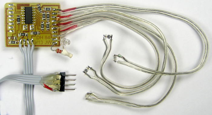 leads. Since I knew the analog inputs would be used for photo transistors, I included their pullups on the board. And since I realized the photo transistors would each be connected with a bit of 2 conductor speaker wire, I put a ground pad adjacent to each I/O line – an excellent idea. Here it is with the first 4 sensors. There’s also a discrete LED on another output pin.
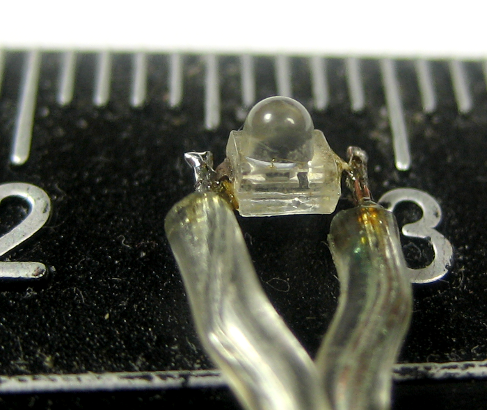 The actual photo transistors were tiny surface mount gems from Electronic Goldmine. At only a couple of mm wide, they were about perfect to peek thru nearly invisible holes in the DH walls. Their downside is that they were old stock, and their leads were badly tarnished, making soldering a challenge. Even my magic Sal-Met flux barely worked. Scraping each tiny lead with an Exacto knife did seem to help.
 Here’s that slave mounted to the back of one of two walls it’s controlling. Each wall has one of the photo sensors (green). Another output pin is driving a pair of red LEDs providing glowing eyes that sometimes peek into a grated window (red). The unconnected wire to the fireplace LEDs comes out a hole in the left wall in the picture. It’s driven by another slave in the basement.
More power! FET driver
The I/O pins on the Atmel chips are great for an LED or two, but are limited to a few tens of mA. For more power-hungry devices (like the fireplace LEDs, or the 100mA 5-chip UV LED that lights the ghost) we need more power.
The cheap, weirdly-packaged MOSFETs are perfect for the job. They’re good for 30V and several amps, with extremely low forward resistance. And since the gate is insulated, you can  drive them with a logic level without even a series resistor like a bipolar transistor base would require. Here’s a little breakout with +5, gnd and a gate signal in on one side, and +5 and switched ground on the other. This one’s fitted with a 2 pin 0.1″ female on the output (color coded, of course).
More slaves!
The order of Tiny85s came in from Digikey (now $1.18 quantity 25), so I replaced the fried chip on one slave (plus another I subsequently blew out). I made up a second Tiny84 slave board, but I walked away from the reflow plate again! Fortunately, this one wasn’t as carbonized as the first, and works OK. One trace did delaminate later, requiring an emergency repair. After that was done, I potted the whole area in hot melt to reduce future problems with it.
Less noise! dumb servo…
A central part of the haunted dollhouse was having the door open magically. Bill hooked up a small servo in the basement right below the door with a piece of spring wire coaxial with both the door hinge pins and the servo shaft, and anchored to the servo horn and the door. The wire was thinner than ideal, but it basically worked.
To drive the servo from a slave, I tried a couple of servo libs. None worked well, so I ended up bit-banging the pulse width servo signal. The I2C lib TinyWireS_stop_check() function needs to be called continuously and frequently, so I put it in a loop using micros() to decide when to flip the output bit. That worked well, at least from a software perspective.
Update 9/17/13: On the road Rachel’s on the way to the NYC Maker Faire and I think a hardware symposium with the dollhouse. It’s not working very well (yet). 🙁
There are 3 photo transistors, but only one works. That one doesn’t trigger well with a flashlight from the outside (the design requirement), but sometimes triggers when it shouldn’t – probably from other lights in the dollhouse. Better aiming/shading would probably fix that. A second used to work, but somehow doesn’t any more. And the third registers with the icrepl tool, but I can’t see it from DH code. That one’s a total mystery.
The MOSFET drivers and fireplace and ghost UV LEDs work fine. There was another MOSFET driving a 12V boost converter to run Bill’s nice little chandelier, but that converter generated too much electrical noise and had to be abandoned.
The two WS2812 NeoPixel RGB LEDs light up their sconces nicely and do just what they should.
The Sparkfun MP3 Trigger board works, but is somehow flaky. It doesn’t always play the correct MP3 files. I can’t imagine how that can happen, and earlier on it worked perfectly. But its main problem was just locking up and refusing to honor further commands. I think that was primarily triggered by electrical noise from the servo.
While the servo had worked in unit testing, once the whole dollhouse was assembled, when the servo was triggered bad things happened on the network. The sound module lockup was a critical one, but other slaves did unexpected things as well. I put 10 or 20 uF caps at various places to quiet it down. First try was directly across the +5, gnd pins on the servo connector. Another was just plugged into one of the hubs to quiet the whole supply line. And another was soldered directly across the power pins on the Sparkfun module. None made significant difference. I don’t know (yet) whether the noise is on the supply lines or on the I2C bus. But it screwed things up big time.
It was with great regret that I unplugged the servo before handing the house over. No door opener! But at least the sound worked, and the rest of the house was more stable. I look forward to having enough time to troubleshoot that noise and fix it once the dollhouse comes back home.
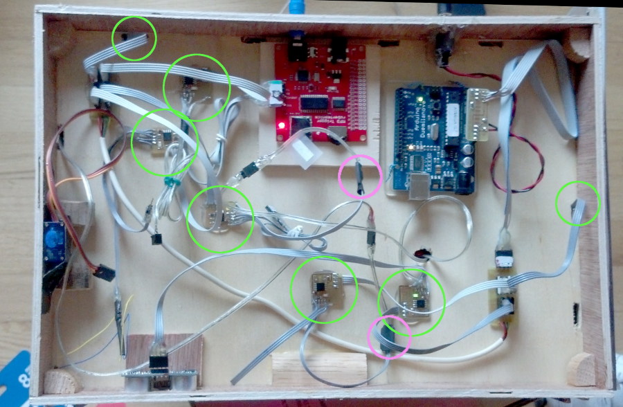 Here’s the basement. There are five Tiny85 slaves there, plus network wires disappearing into the walls for two more Tiny84 slaves (green). The MOSFET drivers for the fireplace and UV ghost LED, covered in heat shrink, are circled in pink. The red SparkFun MP3 trigger’s 3.5mm output jack is accessible through the back wall (top of picture). The blue door servo sits glumly on the left under the door, with its cable disconnected. An ultrasonic distance sensor looks thru holes in the front wall (bottom of picture). And of course there’s the Duemilanove, with a little breakout to pick up the I2C lines on A4, A5 (with pullups) and power for the network hubs, and power in from a 2.1mm barrel connector in the back wall from a 5V wall wart.
Master software
Since the system is really controlled by the master, I tried to make its code as easy to work with as I could. I suspect there are C++ approaches that would be cleaner, but they’re not my friends yet.
There are 4 parts to the code:
– definitions of the inputs
– functions to operate the various output actions
– “rules” that define the input->action behaviors
– the main loop
The input section abstracts all the details of I2C addresses and physical I/O pin to register mappings. It provides an array of slave identities to be queried, and how to read each one’s input(s). It provides names to refer to each node with inputs. Example names are “doorbell”, “light1”. This code must be written with intimate knowledge of the slaves and what is physically wired to what.
The action functions abstract all the details of I2C addresses and registers for each output. They provide nice boolean options like “on” and “off” to whatever bizzare hardware implementation may be wired to the output. An action function may operate one or many physical output devices. These are the only code that writes to slave nodes. Examples are “rgbled1(color)” and “sound(trackName)”. Like the input section, writing this code requires intimate knowledge of the hardware.
The rules section consists of a function for each desired behavior. That code may look at one or more inputs on named slaves, global variables set by other rules or internal data, including timers. With logic based on the above, it can call one or more action functions or set internal or global variables. While complex functions require clever coding, adding new rules by copying and pasting simple rules like “if input 2 on slave “light1” is above 100, call “sound(HOWL)” requires only basic skills.
The main loop walks thru the array of slaves with inputs, reading and storing every input. It then runs every rule function, so the rules can operate on the latest input information. Then it loops – at a rate of many cycles/second.
Essentially there will be a unique master program for every physical implementation of the network.
There is of course work to be done. The inputs could be further abstracted for individual input pins. The rules might be simpler, and perhaps object oriented. The main loop needs to automagically know the names of all the rules instead of having each rule function manually added. While functional, it is still a work in progress.
Dollhouse doc
Since the dollhouse is going out in public, it should have a little one-page ‘about’ doc available. I wrote up the basics – with a link back to this post for gory details. The latest pdf and Word versions are here.
still lots more to do…
Pingback: Haunted Dollhouse Microcontroller Networking for World Maker Faire
Pingback: rndm(mod) » Haunted Dollhouse Microcontroller Networking for World Maker Faire
Pingback: Haunted Dollhouse Microcontroller Networking for World Maker Faire - RaspberryPiBoards
Pingback: Haunted Dollhouse Microcontroller Networking for World Maker Faire — Blog of MPRosa
Pingback: Embrujada Dollhouse Networking microcontrolador para World Maker Faire - | Indagadores |Seguridad informatica |Seguridad en internet
Have you looked at the Trinket? Would be a good development platform.
http://www.adafruit.com/category/167
Yeah, Tiny85 is a great embedded platform, and several people have products based on it. Another is the Digispark. That one has the USB male etched on an extension of the PCB. I bought one of those just to be able to show commercial offerings in a Tiny85 class. I suppose I oughtta get a Trinket, too.
I’m thinking of having some cheap batch board house make up a bunch of Tiny85 boards for my own use (and, at cost, for the use of W88 and class people). They’d be nicer and a little smaller than what I can make. Trinket/Digispark give me some ideas how I might alter mine.