Remote Halloween Candy Delivery System

Thanks to COVID, Halloween is weird this year.  A ‘touchless’ remote candy delivery system was in order.  Due to some misunderstandings about whether the system would be appreciated, it became a very 11th hour project.  I started around 1PM Halloween for a 3:30 Trick-or-Treat start time.  I missed by 45 minutes.  Could have been worse.

Boo Boy

We happened to have a really cute Halloween decoration a friend of Lauren’s had given us many years ago.  He’s stood in a plastic bag all these years – just waiting to be called on.  Today was the day.  He was going to get to hold up the output end of the remote delivery pipe.  Some assembly required.

PVC to the rescue

Do we have anything that would serve as the delivery device?  Laur had seen a woman strapping some flexible corrugated tubing to a banister for this purpose.  Corrugated is sub-optimal if you want things  to slide smoothly through the tube.  But there in the basement ceiling was a piece of 2″ PVC pipe.  That would do.  (There’s lots of 1.5″ pipe, for emergency sump piping, but that’s a little too small.)

The doorbell problem

Even if I could get Boo Boy to hold one end of the pipe securely and the house to hold the other, a showstopper was the doorbell:  If a Trick or Treater had to come right up to the door to ring the doorbell, it kind of defeated the ‘remote’ part of things.

To keep the kid at a distance, she’d need to be able to ring the doorbell from in front of the front steps.  And in addition to making noise inside, the button and mounting would need to be mechanically robust enough for kids to hit and not break.  Yeah, I could certainly invent a way to do that, but it would add to the project.  That was part of what put the project on hold.

After some other misunderstandings were cleared up, I decided I could figure out something to do about the doorbell, and I could start construction.  Unfortunately, Trick-or-Treat hours started in a couple of hours.  Better hurry.

Construction

Boo Boy arm

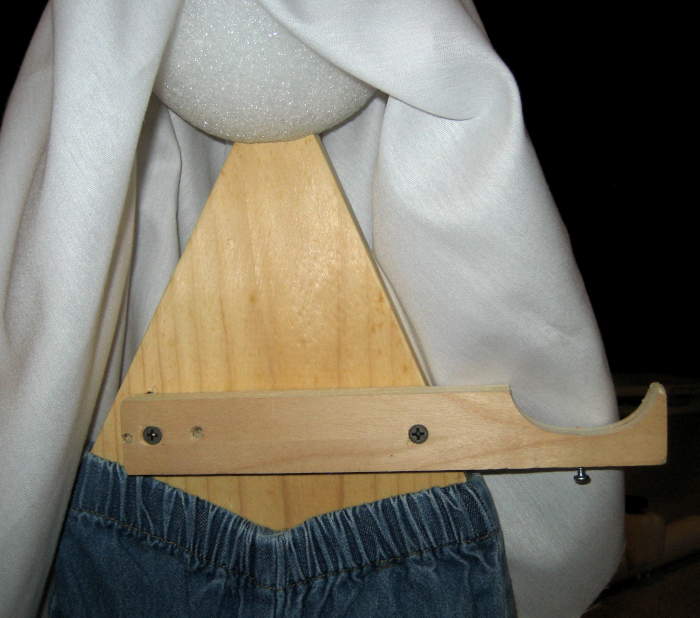
By design, Boo Boy didn’t have visible arms.  But his torso was a piece of wood and hidden under the sheet, so attaching an arm should be easy.  First tries were too long, but cutting it down and reattaching was easy.

The bandsaw cut a roundish notch for the pipe.  The ideal way to attach the pipe to his arm/hand would have been a zip tie thru the sheet, but I didn’t want to damage anything.  I just bunched his sheet up behind the arm and hooked a zip tie around a screw on the bottom.  Worked out acceptably.

Boo Boy stand

I’d found a screw in the screen door frame that should provide fairly sound mounting in all directions, as well as locating the pipe high enough for a good slope.  But while Boo Boy could stand OK, and could provide good vertical support for the pipe, he couldn’t guarantee much lateral support.  (Front-back wasn’t much of an issue if the pipe were well attached to his hand, as the top end was well anchored to the house.)  It’s windy today, adding to the lateral problem.

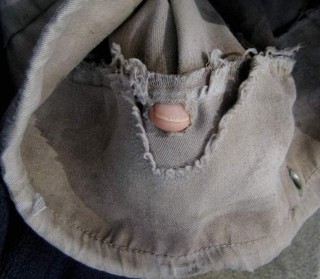
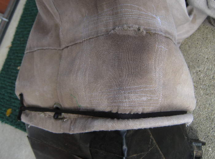
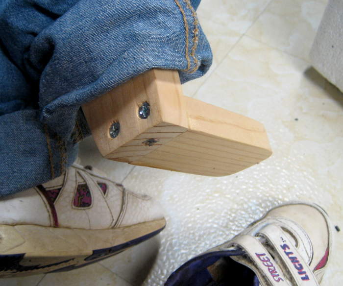
When I took off his shoes, I found good news:  solid 3/4″ legs plus nicely screwed on foot stubs.  While I wanted to avoid visible alterations, driving screws up through his shoes was fair game.

Drilling through his shoes was more exciting than expected.  Maybe that hard layer was a PCB for the ‘Street Lights’ part of the shoes?

I found an old white melamine shelf just the right size, and with a few successful measurements, succeeded in driving 2.5″ screws thru the shelf and his shoes into solid leg wood.  That provided just the lateral support I was hoping for.

An additional plus is that it provided what I thought would be a great place for a sign for the button.  (Wrong.)

Enhanced candy insertion opening

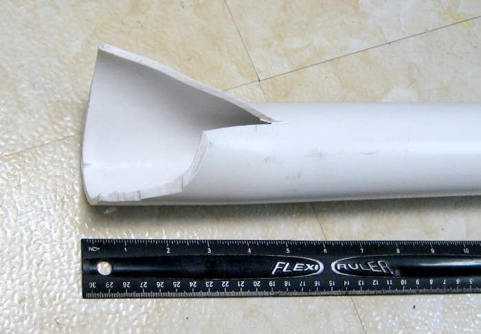
My vision (mostly used only late in the day: Laur was sitting on the porch for the daylight ToT hours) was that candy would be inserted into the pipe from a barely opened screen door.  To make that more convenient, I slit one side of the pipe for 5″ or so, and heated the end halves with a heat gun until with a gloved hand I could splay it out into sort of a funnel.  Did each side separately, but it worked about as planned.

Robust pipe mounting

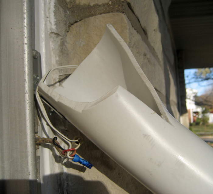
I made a little bracket to mount the end of the pipe to a convenient screw in the door frame.  The mechanical mounting part of that was fine, but then came the first of two unforeseen issues:  The ‘funnel’ very effectively kept the screen door from closing.  I’d done a first pass at hacking the most egregious door blocker off (with a jigsaw) in this pic.  That still wasn’t enough, so the door remained ajar.

Door bell

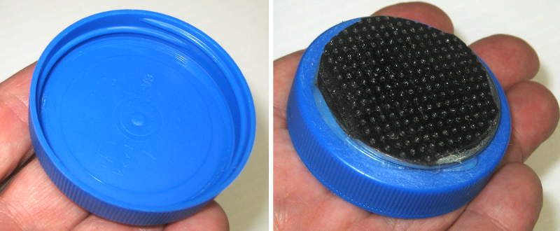
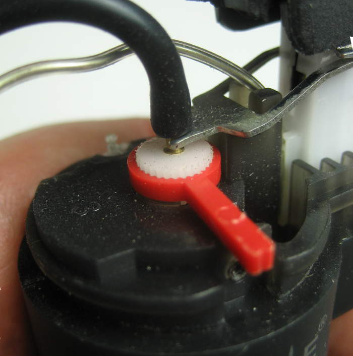
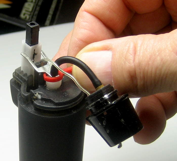
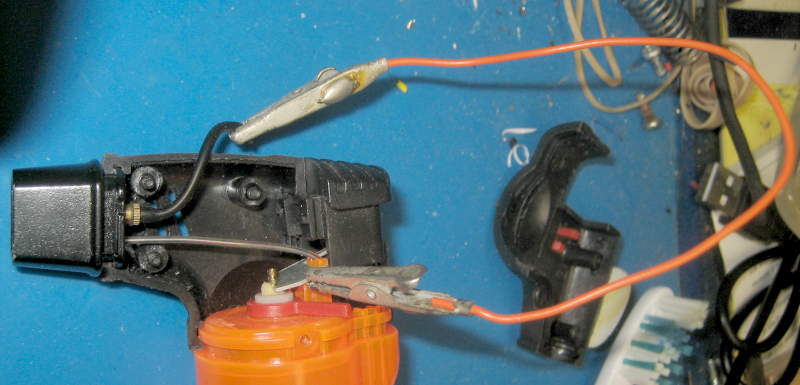
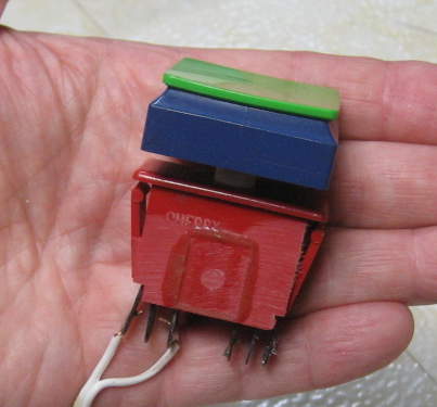
After the pipe was nicely mounted and functional (though still blocking the door), it was time to figure out what to do about a doorbell.  Looking through the boxes of switches, I came across a perfect candidate:  A great big clackety momentary contact DPDT switch.  The shape and layout of the switch part were completely wrong, but I really liked the button.

The original plan had been to put a piezo or something and a power supply inside the house connected to the button to notify us when a ToTer was there.  But at some point along the way, I’d unconsciously decided rather than that to just connect to the house doorbell.  It was right there, and how hard could it be to pull the doorbell button and temporarily splice a couple of wires?  (Answer: harder than planned.)

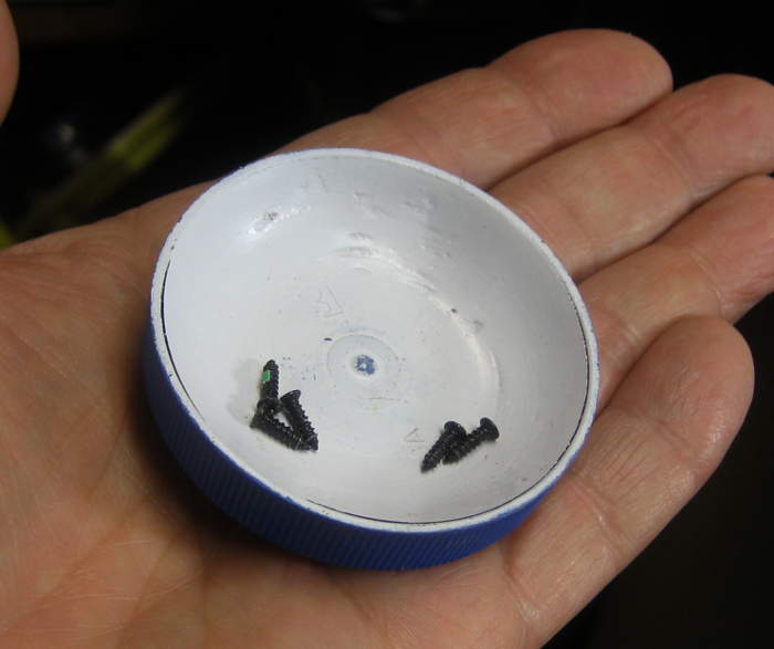
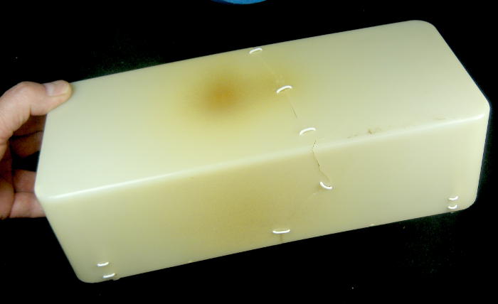
A minute later, when it was time to actually figure out how to mount the switch (remember, this was a crash project!), I looked around for something solid I could build the mount from.  And I spied it:  a block of closed cell foam!  The one I found wasn’t quite right, but with very mixed feelings, I went to the out-of-control foam/bubble wrap/etc shelves.  Sure enough, there was a perfect large chunk of stuff I could cut just what I needed from.  Boy, it’s a good thing I hadn’t gotten around to purging that shelf as I’ve been planning to do for a year or five!

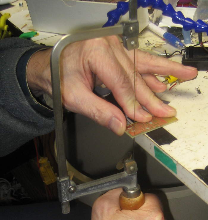
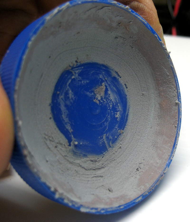
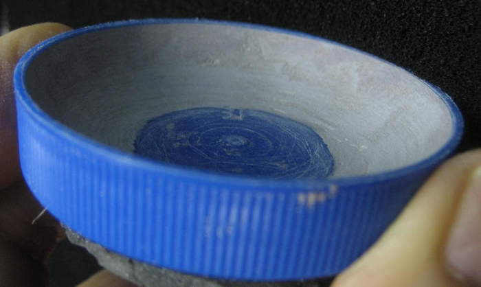
Closed cell foam is really nice to work with for crude stuff like this.  A jeweler’s saw easily cut the semi-cylindrical notch for the PVC pipe it would mount to, and an Xacto knife made quick work of cutting out the deep rectangular 0.5″ x 1.5″ hole for the clunky switch body.  The hole went all the way through so the terminals rested on the pipe.  Boo Boy could provide acceptable vertical support so the switch wouldn’t feel mushy.

I brought a roll of #20 solid zip cord I don’t particularly like out to the mounted tube and chopped off a piece about the right length.  The tabs on the switch were very old and oxidized, but hitting them with a Dremel cutoff wheel fixed that in a few seconds.  I soldered the wire to the terminals, fed it thru the hole and stuffed the switch into its final home.

Slobbering contact cement generously all over the inside of the cutout for the tube allowed me to momentarily press the foam to the PVC pipe where I wanted it to be mounted and left just the right amount of cement on both parts.  I left them to dry for a few minutes while I looked at removing the existing doorbell button.

Then came the second unforeseen problem with the door-frame mount of the top of the pipe:  It completely obscured the doorbell button.  I had to take the dumb pipe off again to get the screws out of the house button.  It only took a minute or two, but grumpf.

With the button off, wires exposed, pipe remounted to the house, and foam and switch stuck to the pipe down at the kid end (further secured with zip ties), I wrapped the wire a few turns around the pipe and cut it to length.  While the first one worked, I can’t believe I couldn’t get the second pair of wires connected with a wire nut.  I tried a couple of gray, a couple of blue, added extra wire to bulk the connection up – all failed.  
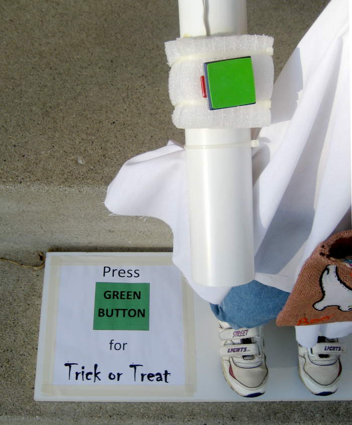
Finally found a small crimp connector and that worked.  Pushed the green button, doorbell sounded, as expected.  Good.

But it still needed a sign to tell ToTers to push the button.  That was quick, too.  Unfortunately it turned out to be sub-optimal:  For too-young-to-read kids, the accompanying parent/coaches were too far behind to see the sign.  Nice try.

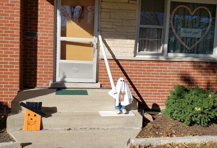
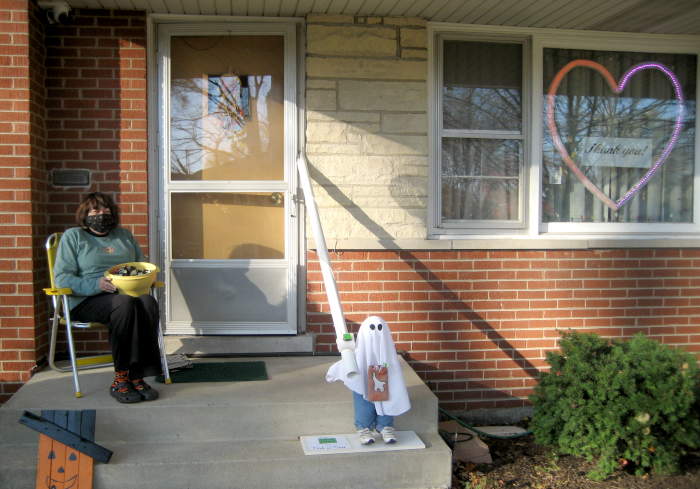
I’m done!  Lauren sat outside for the first couple of hours, sometimes reaching up and sending candy bars down the pipe, but dropping treats whose packaging wasn’t compatible directly into their bags.  She saved most of the most pipe-compatible treats, like fun-size Snickers, for after she went inside.  All in all, it worked out quite well.

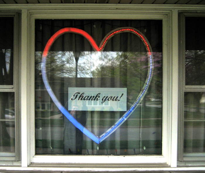
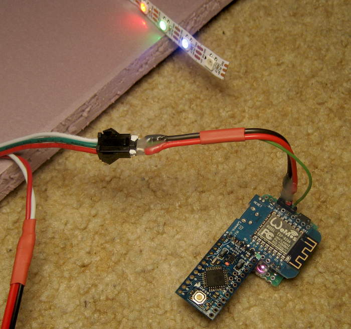
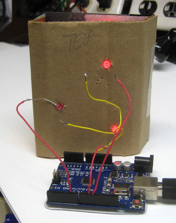
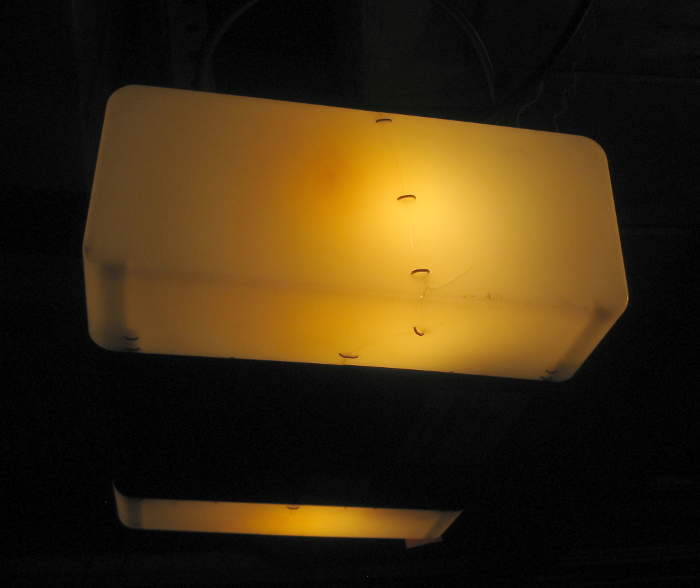
The LED heart ran a special Halloween program of all orange, and beating, lub-dub, with occasional minor bits of eye candy.

Posted in House and garden/snow | Tagged , , , , | Leave a comment

Thank you heart

(This is a quick overview.  Proper build details will follow soon.)

I wanted to put something nice in the window to say “Thanks!” to all the health care and other essential service workers who are keeping people safe and helping life go on in these challenging times.  Sorry it’s starting so late.

Electronics

The heart is some 200 WS2812 individually addressable RGB LEDs mounted on a heart-shaped ring of 1/4″ foamboard.  They draw around 4A from a 5V supply.  An Arduino Pro Micro drives the LEDs thru the Adafruit Neopixel library.  Thanks, Adafruit!  I wrote the code telling it what to do in C/C++ using the Arduino development environment.

Appearance

There have been lots of changes in plan in the 2 weeks between starting and hanging it in the window.  One of the very visible ones is naked vs diffused LEDs.  What I envisioned from day one was a smooth, gentle glow.  I didn’t want the techie appearance of raw LEDs.  The tracing paper diffuser on the left half gives just the visual effect I wanted.

But both my wife and I responded to the brilliant LEDs on the unfinished side.  The phantom-of-the-opera-mask appearance was never planned, but it’s an interesting feature.  While the option of putting the diffuser on the right side remains, I’m guessing it won’t happen.

Behavior

In keeping with the ‘gentle glow’ spirit, the plan was to light the heart with just one color, changing slowly around the color wheel maybe once/day.  Fancier opportunities arose, and alternating days of full saturation and pastels was the plan for a while.

Early in the software development (meaning after it would actually light up), various animations from the Adafruit example code were included.  Other patterns suggested themselves, and although envisioned as static displays, I typically prototyped them as animations, often to help debug code trying to get the LEDs to behave in ways foreign to their linear addressing scheme.

But as we watched it cycle thru the animations still in the shop, I had to admit that it seemed a shame to deprive its audience – neighborhood walkers – of the entertainment of the dancing patterns.

So in a near-complete reversal of the original plan, V1.0 spends most of its time slowly but visibly changing color, with a spot of eye candy animation every 20-40 seconds.

Making it

Frame

While I did have to order a new spool of LEDs, the rest of the parts, including the Arduino and power supply, were just on the shelf.  That meant that the main frame was cobbled together from 6 bits of scrap foamboard.  There were mechanical challenges piecing them together.

LEDs and reflector

The obvious thing to do was to just stick the adhesive-backed LED strip to the foamboard.  Unfortunately, while the strip is quite flexible in one direction, it’s quite inflexible in the direction needed to make it conform to the curves of the heart.

But if I laid the strip on its edge instead of its back, I could easily bend it to follow the heart shape.  I could just glue some little blocks to the foamboard to anchor the strip right where I wanted.  Great!

Well, except then the light coming from the LEDs is going the wrong direction.  If I put a mirror at 45° in front of every LED, I could bounce the light right back where I wanted it.  Some back of the envelope calculations to determine how big the reflector should be, and a plan emerged.

The initial attempt using aluminum foil was way too flimsy, and didn’t work well at all.  Fortunately, I had a big roll of very shiny adhesive foil tape, and lots of 110 lb cardstock.  Based on the dimensions that looked like they’d work, I made up a bunch of cardstock-and-foil-tape 45° reflector strip.


Lots of snips and tucks and glue and adjustments later, the LEDs were shining the right direction.  Here looking straight down on the foamboard, you can see just the edges of the actual LEDs (circled) and their reflections in the foil.  Not perfect, but most of the light is going the right way.

Diffuser

To get the “soft glow” I wanted – long before the half-and-half idea raised its interesting head – I found supporting a sheet of tracing paper over the (reflections of the) LEDs worked well.  A couple of design iterations later, I had a support approach that looked like it would work.

Twelve sheets of tracing paper, a bunch of supports cut from PET packaging, two kinds of glue, and a couple of hours later I had a nice gentle light from half of the heart (plus carefully cut paper for the other half – which will probably never be installed).

Next steps

While the heart is finally in the window, it’s very much still work in progress.  I’m sure it will learn new animations as ideas come up from others (or me!).  It still needs to learn what time it is to automatically fade up in the morning and fade out at night.  Motion detection from the existing cameras may affect its behavior.  Fortunately, teaching it new tricks now doesn’t involve glue or Xacto knives or clamps:  “It’s just code from here.”

Comments are welcome.

Thanks to all our heros who are working to keep us safe and sound!

Development heart, animations

Update 6/20/20:  More progress.  To make it easier to develop more animations, I made up a duplicate functional, though ugly heart.  I didn’t have quite enough LEDs, so there’s a gap at the bottom.  No reflectors – just what light bounces off the pink 1″ foam insulation board it’s built on.  The foam wasn’t quite wide enough, so it has some wings to help hold the LEDs at the edges.  The contact cement I tried to use for the wings barely worked, but the plan B duct tape on the back holds them nicely.

Construction is considerably more ‘casual’ than for the real heart.

To drive it, I made up a little protoboard that connects a Pro Mini to a WEMOS D1 mini ESP8266 (and hosts some level shifters).  The really cool ESP-link firmware on the 8266 provides a web server, so there’s a  browser interface with both the serial console and ability to upload code!  Part of the intent of that was to use it to control the real heart so scripts on the security cam server could control the heart’s behavior.  That hasn’t happened yet.

But the dev heart did allow me to write some more animations.  Those are now rolled into the real heart.  It now does the animations in order (rather than randomly).  Still no knowledge of what time it is, so there’s just a mechanical timer to turn it on in the morning and off in the evening, instead of the nice fade-up and fade-down it should have.  Maybe some day.

Surmounting some photographic and video-production challenges, I did get a little video made up of all the animations to date.  It’s here.

Auto on-off!

Update 8/4/20:    The only robust way for it to turn on and off at appropriate times in the long term is for it to know what time it is and what time sunrise and sunset are.  A DS3231 Real Time Clock module provides the first part.  I put a little protective cover over one.

Adding a new I2C pigtail to an Arduino Pro Mini let it talk to the RTC as well as the heart.

For sunrise and sunset, I found dmkishi‘s very nice Dusk2Dawn library, and gave it my latitude, longitude, and time zone.  Calling that with the date gives times for sunrise and set.  With date and time provided by the RTC, it could now decide when to turn on and off.  I told it to start 15 min after sunrise and turn off 20 min before sunset.  Seems to work fine.

But what about Daylight Saving Time?  I had set the RTC during summer (a year ago), so it was still on CDT.  I told Dusk2Dawn that it was currently DST.  Works fine.  But the clock module doesn’t know about DST, and makes no automatic adjustment.

So if I take the simple path of not resetting the RTC when we go back to Standard time, and if I take the simple path and don’t change the code to tell the D2D lib it’s no longer DST, it should work seamlessly across the time change.  For half the year, we’re lying to both, but it all cancels out. 🙂

Halloween update 10/31/20: It seemed appropriate to do something Halloween-themed with the heart, just as a one-day special.  It can do orange.  Fine.  And it’s a heart, so it could ‘beat’, lub-dub.  Fine.

But what can you do with a monochromatic palette?  If it wanted to express ‘happy’, it could ‘sparkle’.  Big blobs like the main heart routine’s ‘happy’, but just on/off sort of works.

OK, you could add purple, which helps.  Actually in A-B tests, I chose random orange/purple blobs over orange/off.  A little progress.

And it’s Halloween, so a little gore is OK, and it’s a heart, so blood.  For a few more LEDs added off the very bottom, blood could drip out and fall into a puddle below.  Blood could leak out of some starting spot, run down the side, and drip out.  Maybe the heart gets a little fainter/less orange as it bleeds?  Maybe its heart rate increases in desperation?  Maybe it just fades to black as it dies?  Kind of gross, but it is Halloween.

And purple.  Maybe it starts with a purple wart on one side.  The wart grows, and eventually covers the whole heart.  When the evil purple has completely taken over, maybe it beats with just lub.

Maybe a little orange blob then develops, and breaks off, and falls around to the bottom.  But it keeps going up the other side.  Gravity is visible, speeding the blob as it falls, slowing going up.  But with each cycle, it grows, and bounces up a little higher.  After while it makes it all the way to the top, just makes it over, goes down the other side and starts going around.  As it goes faster and faster, it grows more, and with each pass the purple fades a little more until the orange has taken back as rightful ruler.  It sparkles with joy for a moment, then goes back to its lub-dub.

A couple of color wipes are possible.  Maybe it fills from the top down, with orange on one side, purple on the other.  And when it’s full at the bottom the color wipe switches sides, orange replacing purple and purple replacing orange.  It could stay that way, split vertically, beating for a little while.  Next time orange and purple switch sides.

Reality

I got part way.  The old dev heart was again invaluable.  Glad I hadn’t gotten around to tearing it down.

Brightness is computed with 8 bit integer math.  Using the global brightness function to implement the heartbeat drastically changed the color, but settled down to a color that pulsed consistently.  I didn’t do the numerology to see exactly what was happening, but I expect the stable colors were zeros in the low bits.

To get a usable heartbeat, I pre-populated a five element array with good first generation brightness values that maintained hue, then cycled thru them with a 40mS delay between, repainting the whole heart with each in turn.  Fortunately, the protocol is fast enough that that approach worked nicely.

I got blood running down the side, though never got as far as the added ‘dripping’ LEDs.  No purple warts or orange campaign to take back over.

When I tried it at full brightness in the window and viewed from outside, the color was way yellower than I expected.  I even wondered whether the red LEDs had lost brightness over time.  I tweaked the #defined ORANGE value to something that appeared much more like orange.  But when I got that back on the dev heart, it looked quite red-orange.  And the blood was almost invisible against that color.  That was part of why the bleeding never happened.

I did get a couple of color wipes running, plus the orange/purple ‘happy dance’.  While the original plan was for Halloween only, I backed off and decided to allow it the day before as well.  And then, when I actually had a few animations, I started it four days before, planning on adding actions.  That never happened, and those few behaviors ran all the way through Halloween.

I did do a little hack to let it run past dark on Halloween, dimmed to 100/255 brightness.  It went back to normal programming the next day.  Interesting.

I took a video of its final patterns.  I hope to edit that down to a reasonable length and post it soon.

Posted in LED window heart | Tagged , , , , , , , | 2 Comments

Nomorobo First Ring Blocker

We use Nomorobo for our VOIP home phone, and I’m very happy with the service.  (NMR: Your phone provider’s simultaneous ring service routes calls to both your phone and NMR.  If NMR decides it’s bad, they pick up, and you hear only that first ring.)

But you know, if we could just skip the first ring on all incoming calls to our phones, all the annoying one-ring NMR blocks would go away.  (Yeah, they’re much better than having the call come thru, but still annoying.)  Yes, it would make legit callers endure one more ring before we answered, and I’m willing to make them pay that cost.  But then we could always get up to check the phone on the first ring instead of wondering.  Sounds like a winner!

A Plan forms

So I found the MGCOM FRS22100 Nomorobo first ring blocker.  Self powered, 5 stars on Amazon.  Perfect – I’ll buy one today!  Except that you can’t.  No longer available.  And my best Google-fu couldn’t find any NOS or even used ones on Ebay.  Bummer.

I wrote to the company, but never heard back from them.

A New Plan forms

OK – this is just telephone stuff.  I should be able to make one.  Yeah, Yet Another Project – but it would stop all those rings!  And how hard can it be?  (Famous Last Words)

The device needs to be right after the VOIP controller/modem.  (That last portion before the phone jack is the Analog Telephone Adapter, or ATA.  Thanks, David!)   Caller ID info is sent between 1st and 2nd rings (in Bell 202 FSK here in the US).  If I could disconnect all the house phones as the first ring starts quickly enough that the phones don’t start to ring, and if I reconnected just after that ring, but before the caller ID, (and if the phone doesn’t barf at losing 48V), I think that would work.

The best solution

Since absolutely all the stuff that comes out the RJ11 phone jack on the back of the Xfinity gateway is generated inside that box – not coming thru miles of copper outside – there’s a perfect place to implement no-first-ring:  in the software in the gateway.  It would just be a couple of lines of code.  But that’s not gonna happen.  Easier to just build some hardware. 🙁

Not quite POTS

Real Plain Old Telephone Service is formally not ground referenced.  But while what comes out of our Xfinity VOIP gateway has to look a lot like analog POTS to work with whatever phones people hook up to it, it doesn’t have to play by exactly the same rules, so I need to check it out.

I measured 48VDC across the line on-hook (as expected).  There was ~10V same polarity off-hook – fine.  On-hook, there was 3VDC from 3rd prong ground to one side and 51V to the other.  Don’t know whether the gateway or our local phones did that.  Grounded the 51V line arbitrarily thru 10KΩ, and it only dropped the voltage to maybe 46V, so there’s some actual connectivity to ground.  So my stuff needs to be not ground referenced.  Noted.

I need to see the actual voltage waveforms on the line to design the circuit.  My shiny new Hantek DSO is perfectly suited to that task, but unfortunately, it’s  ground referenced.  An isolation transformer fixed that.  I put a full wave bridge on the line (as described below) and recorded a ring.  (I think this is the first pic directly recorded by the scope to USB I’ve used.)  We see alternating amplitude of the half cycles, but not the 90VRMS superimposed on 48V we expect.  It’s more like 70VRMS (200Vpp) on top of 5VDC.  But now we know what we’re working with.

Timing

If the ring is 2 sec @20 Hz, that’s about 40 cycles (80 after full wave rectification).  Each half cycle is 25ms.  If the code + relay could react within say 5 ms (1/5 of a half cycle), I’d guess it would work.  (Guess is the operative word:  “The test is the test.”, as Ziggy would say.)  But now I have a ballpark time budget target.

Relays

A relay seems the suitable way to disconnect/reconnect all the house phones.  But the timing is critical: I have to sense the ring very quickly, and then open the circuit very quickly.  And then at the end of the ring I have to reconnect before the caller ID starts.  How fast is a relay?

I checked out two small 5V relays from the junkbox.  The first was clearly a reed switch – just SPST, and it reacted to a magnet nearby.  The second was DPDT, so presumably had a more traditional mechanism inside.

The reed switch closed in ~150 µsec, with another 100 µsec of bounce.  That’s plenty fast enough.  Release time was harder to measure, but I think it’s ~10 µsec even at 5V.  The second one had similar times – sorry for missing data.  But they’re plenty fast enough.  Surprise:  The DPDT relay coil is polarity sensitive!

Failsafe

Having the phones stop working because some wall wart I used (or my code!) failed is unacceptable.  So a failsafe design requires the relay to be normally closed, ruling out the reed switch.  And if I have a pair of the DPDT contacts in parallel, it’s even more robust.  We use the DPDT relay.

Circuit design

Let’s just start with a bridge rectifier on the line and use the negative output as local ground so we’re only dealing with one polarity.  One side of the line to the rest of the house goes thru the NC relay contacts.

The observed ring voltage is ~104V max.  (Every other half cycle is ~95V.)  We can divide that down to work with say the 1.1V reference on an Arduino.  We don’t get any additional info from anything over maybe the first maybe 10V (above 48), so exceeding the max of the A/D is OK, as long as we don’t exceed the abs max voltage on any pin (Vcc+0.5V).  If it works, it’s just code from there. 🙂

Arduino data

The first prototyping was with a normal 328P Arduino Nano. I hooked up a bridge rectifier and voltage divider and had the Arduino spew raw A/D values at 115200 to a laptop running on battery (and so isolated from ground).  It uses 5V Aref instead of the intended 1.1V – oops.  I suspect the circled part is the caller ID data.  If so, I have around 600ms from ring stop to data.  I can easily get the relay to close again in that time.  I hope that’s enough for the phone to get over saying “What the heck just happened?” on losing 48V for a couple of seconds and listen for the ID.  I hope it doesn’t expect a ring first…  (It does.)

Here’s another run, of a full cycle including pickup, and with analogReference(INTERNAL).  Interesting, but the real value is that now I can set my thresholds.  The 48VDC idled at 848 counts, so how about 1020 for high threshold.  Off-hook was 159.  So say < 400 for that.  (That glitch will bite us later.)

First proto

OK – made up a prototype.  Remembered to put a diode across the coil.  There’s still a button from the data collection runs, but it will go soon.  While the contacts of the relay – if you want to parallel them as I do – are “breadboard friendly”, the coil contacts are not.  Had to solder some leads on – grumpf.  (And discovered they’re polarity sensitive!)

Both male and female phone connections are quite fragile, but with luck this will only have to survive or two connect/disconnect cycles.  (Try a dozen.)  The female is from an old DSL filter.  That Nano with header pins along (only) one side has come in handy a couple of times.

First live observations

Took longer to get the code working than I hoped/expected. 🙂  Some dumb stuff, a math error (integer rolling average without roundoff correction), and a real logic error forgetting that line voltage goes very low (below off-hook threshold) every half-cycle of ring, which screwed up off-hook detection.

Grabbed a nice 5V wall wart and verified that it was properly isolated.  While it showed 33VAC between output and line, with an arbitrary 10K in parallel with the meter that voltage went away nicely.  We have power.

Caller ID issue

Phone behavior is a little different:  It seems to announce the caller ID out loud when it didn’t before (although I had set it to do so).  And it doesn’t display the caller ID until after the second (first heard) ring.  I think that should be mostly OK.  But it looks like it doesn’t listen for caller ID until it’s heard a ring, so my efforts to reconnect quickly to let that first caller ID thru were wasted.  Boo.

But if it takes most of a ring to walk close enough to the phone to see the display, maybe the timing isn’t too much of a problem.  I guess we’ll have to live with it a bit to see.  (It’s fine.)

False positive glitch

When I put the proto back in, going off hook and back on registered as a (1-ring) NMR block.  Huh?  Captured this directly from the phone line, starting off-hook, going on-hook.  There’s a 10V (above 48V) glitch, probably enough to hit 1023 on the A/D and register as a ring. And this would happen every time we made an outgoing call (or presumably answered a legit call).

Looks like it happens 14ms after going on-hook.  Yeah, the positive glitch is only about 4.4ms, but I hope that 35ms negative lump won’t mess anything else up.  Looks like it’s probably low enough to register as off-hook (briefly).  (I’m starting to love these scope captures!)

After most of a day stewing and messing with it, I realized that by simplifying the state machine in the code (rather than adding the two new states I was trying) it would all work.  Simplifying is such a nice word.

Reporting

Immediately following the first mostly-successful test, alter ego Mr Data rose from repose wanting to know how many successful blocks had occurred.  Shoulda known he’d ask that.  Fine.  But how to display it?

Yak shaving: LCD display

I’ve wanted an I2C LCD for a long time for just such situations.  (With a keypad, but didn’t need it this time.)  I dug around in the LCD box and found an I2C backpack laid out for 1602 LCDs.  And a 1602.  Could it be that easy?

Well, startlingly, yes.  I soldered the backpack on, ran the I2C checker on it and it saw a device respond on addr 0x27.  The chip on the backpack was a PCF8574.  Looked up its addr – 0x27!  Found a lib for it on my machine, ran the example code and it came up and showed stuff!  Put a little protective PET backing on the module and started writing code.

Cut and pasted from the LCD example to the new Nomorobo2.ino (first saving the working version, as is proper).  Added a few jumpers to support an I2C connector, loaded the code on it, and the display came up!

Wow – that was way quicker than it could have been.  We have an operational proto with logging of rings blocked and NMR events!

</Yak shaving>

When I put it back in service, the LCD displayed the banner, but when I did 2 test calls, the display showed both as multiple rings (even though I hung up after 1 ring, NMR style, on one).  Oops – I put almost all the code in to handle NMR events correctly.  Easy fix, but do I really have to disconnect, haul the ever-more-fragile proto back to the PC, load new code, haul it back and reconnect it?

No.  Easier to just schlep the laptop out there and balance it on the water heater again.  Not too hard.

Loaded the new code and it worked.  Replaced power with the wall wart, and I think we’re in business.  After the first full day of use, it shows 10 rings and 6 NMR events.  I suspect that’s correct.

Improvements!

I guess that can’t really be called scope creep, since the requirements weren’t very clear in the first place.

Final hosting

Of course more permanent hardware will be needed.  A small PCB with a Tiny85 seems likely.  Different voltage divider for the 2.56V ref, but that’s easy.  A significant consideration is preventing the ICSP programming from failing due to those pins also being connected to something else.  The relay coil is probably a killer that way, so it will go on one of the Tiny85’s precious unused pins.

It would be nice to have it report (via software serial and an opto isolator) what’s going on to the house monitor  RS485 network.  There’s even a node only a few feet away, so not bad to connect.  But it’s another project to add the new functionality to the node.

I’ll take the cheap way out and let it talk to another Arduino with just the LCD.  If I use the same wall wart, won’t even need an opto isolator.  We have a plan.

Production PCB

Around 1/6/20 I made up a PCB for a Tiny85-based ring stopper.  The first error, realized after etching but even before drilling was no snubber diode for the relay.  I should be able add an SMT diode if I give up the LED across the coil and use its resistor pads.

The barrel power connector had flat terminals.  Used oval pads and tried drilling 3 holes for one; fail.  What worked was using a jeweler’s saw and a very thin blade – just fits my standard #64 hole.  Took only a little while.

The slots are ugly, but functional.  Took the blade out of the first hole maybe 4 times to check if it fit.  Second hole was maybe only 2 tries.  I need to remember this approach for the next time I have a flat terminal for a thru hole.  (Of course hindsight says we didn’t even need that connector:  could have powered it thru the ICSP header.)

Voltage divider

More tries at the math than I expected said a new voltage divider of 33K/1.5K should work.  (It was close, but not quite close enough.)

PCB

Burned Tiny85 fuse for clock not DIV8; then it worked full speed.  Screwed up and chose RST pin to connect LED to, so it was on all the time.  Did nice air wire fix, but to the wrong place.  🙁  Unsoldered, did better second time (to pin 7/D2/SCK).  Grumpf.  Relay, serial, LED all seem to work.

Found a safe place to drill a hole for a tiny zip tie for strain relief, and added the male pigtail.  I think it’s hardware complete.  (Turns out, no.)

Got hardware ‘hello world’ of sequential blink LED, LED on serial port, click relay to work.  Very good.  Got SoftwareSerial working at 1200.

Voltage divider final tuning

Tried to verify analog reads with old HP supply connected to tip/ring in, printing analog values to serial.  Learned about analogReference( INTERNAL2V56 )  vs INTERNAL2V56_NO_CAP.  Oops – that supply is ground referenced.  At least it doesn’t look like I hurt the chip.

Tried actual line in connected to VOIP line to get A/D values to set thresholds.  Used laptop on battery with USB serial adapter.  Didn’t bother with ring, as 1023 gives no info.  On hook/48V-> 885 A/D counts.  Off hook 175 counts.  I have my thresholds.

But would it exceed max Vin on ring?  885 counts (48V) is 86.5%FS, so FS (=2.56V) means 55Vin.  That’s 107 Vin for 5V at the pin – at the ragged edge.  Abs max value can  go to Vcc+0.5V so it should withstand 118V.  Our peak is ~104V.  But the headroom is uncomfortably small.  Boo.  But I’m going to use it anyway.  (Does that mean boo me?)  If I had a 1206 1.2K for the divider I’d use it, but I don’t.  A quick Ebay search found nothing helpful in the US.

Hardware hack

Hmm.  If I put another resistor in series with the incoming line voltage – just to the bridge, not in series with line out – I could reduce the voltage the Tiny85 sees.  That bridge is looking into 34.5K.  I can easily get as much headroom as I want that way.  And since the A/D has way more resolution than I need for my 3 possible line states, the lower resolution isn’t a problem.

AND – there’s a place on the board I could hack one in!  One trace cut and grind out some fill.  If I’m concerned about exceeding safe voltage, I have no choice.  So – how much headroom do I want?

Wow – I just got an extra 6% headroom!  Feels much better.  Hmm – I have a 1206 39K.  I could have just replaced the 33K top of the voltage divider with that and gotten more headroom, more easily.  Oh Well.

Was this just my fault for not making the divider right in the first place?  The math above (->33K) is correct.  I guess tolerances just were the wrong way.  Oh Well.

Now I need to run it up connected to the real line to verify peak voltage on the analog input pin with a ring.

The scope reported 2.08V on-hook (fine) and got a single trace ring snapshot.  The key bit is Max of 4.4V.  Yay – we’re safe!

And a double check of 2.08V idle gives 2.08/2.56*1023=831 counts.  Just about what the Tiny reported via serial.  Great!  Well, as long as I can remember not to disconnect power while it’s plugged into the line.  That 2.08V on-hook is still above abs max Vin with Vcc=0.

Results

Sorry for a closing pic of the device just hanging by its wires, but until it gets a case and an opto isolated node on the monitor net to report to, this will have to do.

But it’s up and running, reporting its results, and we haven’t heard one of those NMR one-ringers in the several days since the first proto went online!

Code and board info

Inspired by a question from a reader of this post, I’ve put the code for the main controller, plus what runs the LCD up on github.  In the off chance they’re useful to anyone else, the Eagle files for the PCB are there, too.

Posted in Miscellaneous | Tagged , , , , , , , | 15 Comments

Bondo parts tray

You always need some small container on the bench to hold the screws you just took out.  Mine are often plastic jar caps, but they’re light, slide around, and let screws escape (often to the floor).

The first serious fix was to glue a large washer to the bottom for weight, and then a layer of non-adhesive but very sticky rubber on the washer.  That accomplished the goal – it never slid around at all.

But getting screws out was a hassle, with the threads trapping the screws.  An ideal tray would have a smooth cross section.  But how to make that?

I’m sure many colleagues would have 3D printed it.  Fine.  I chose – Bondo!  I think it took 2 tries.

Some sanding, and I had this:

Pretty good, but smoother – and glossy! – would be better.  So some gloss spray paint, and I had this!

Works great, and it’s easy to see the parts it’s holding.  (Well, I guess, unless they’re white.)  It’s earned permanent residence on the bench.


Posted in Miscellaneous | Tagged , , , , | 2 Comments

Butane torch repair

I bought a cheap butane torch on Ebay to keep at the space (yeah, in violation of the “no pressurized gasses” rule, but stashed away in my box).  Worked fine, rarely used.

When I wanted to bend some laser cut acrylic to make  cases for 485 net nodes, it worked fine – until it didn’t.  It just wouldn’t stay lit.  I brought it home, refilled it and brought it back to the space the next week, but it still wouldn’t light and wouldn’t even stay lit if lit from another flame (butane lighter in electronics lab).

Failing to try the obvious small screws, and thinking it was all but junk, I tried to unscrew the obvious metal tip housing.  It turned, but didn’t feel like it was unscrewing.  No more acrylic bending for you.  Grumbling, I brought it back home.

I finally removed the little screws, (seen here in my nice Bondo-filled plastic cap parts tray).

Kudos to the manufacturer for making all 5 screws the same size. 🙂  When I popped it open, I was met with this interesting view:

It wasn’t too embarrassingly long until I realized this was the result of trying to unscrew the tip.  Not much gas gonna come out like that.  Fortunately, nothing was damaged, and it was an easy fix.

Side question:  The insulated wire is clearly (ha!) for the ignition spark.  But where’s the return path?  Is the black tube conductive?

But it still didn’t light or stay lit.  Butane torches and lighters are pretty similar, so after lots of YouTubes and nut-case lighter people forums, I learned:

  • Many say you should vent it (hold with fill valve up, depress valve with small tool, let some gas out.)  Recommendations vary from “bleed it empty every time before you refill” to “every several months”, to “when needed”.
  • There are religious arguments about fuel, with comments running 20-1 in favor of triple- or quintuple distilled brands.  Disbelievers point out the 5X stuff is really only distilled 3 times, with just filtration steps in between, so not really 5X.  <rolls eyes>  Ronson (what I have) is pretty universally put at the bottom of the list.  And then the 5% guy pipes up with “I use nothing but Ronson, and haven’t had a problem in 10 years.”  Hmm.
  • LOTS of people complain about short lifespans of even name brand (Bernzomatic et al) torches.  The ignition systems are the biggest complaint.  My igniter still works fine – the torch just doesn’t work.
  • One seller of torches (and 5X fuel!) started a video with half a dozen assorted torches customers had returned as not working.  He claimed “There’s nothing wrong with any of these.  They just used bad fuel!”  Hmm.

Because mine would ‘pop’ frequently, but just never stay lit, as I thought about it, it started to feel like a fuel problem.  If there were really some air in the tank, the mixture wouldn’t be right, and that might result in the behavior I was seeing.  (OK, if the flame didn’t back up into the air-sullied tank and explode first.  Which it hasn’t done, reflecting poorly on this hypothesis.  Fortunately.)  But the ‘purge’ idea resonated anyway.

Tried a couple of purge cycles – no change.  At least that’s consistent with not exploding.

The nozzle is a venturi/reverse carburetor (airburetor?) sucking the air in.  Might those passages be blocked?  Using another suggestion from the forums, I blasted it with compressed air.  No change.

I’d seen demos of torches with mixture adjustments go to a soft yellow flame with the air turned off.  Mine doesn’t have that, but what if I blocked the air inlets?  With blue painter’s tape putting it on ‘full choke’, I got this surprising but unsurprising (!?) result:

Slowly peeling the tape away gave a normal looking flame.  More air, and it blew out.  Hmm.

Playing with the red gas volume adjustment, it would close all the way off, and seemed closest to working with it on full.  Is there some further hidden adjustment?  Thinking back on what I’d seen when it was open – was that red adjustment on a splined fitting?  <opens it up again>  Sure enough!

I set it to about mid way, lifted it off and set it back so the red lever was close to its lowest setting.

Moving it back up to full throttle, it lit!

I moved it again to give myself a little more top end, put it back together, and it works again.  That’s great.  But why did it fail?

My best guess is there’s some crud (See?  I told you that Ronson stuff was crap!) in the gas path and the valve needs to be open more than when new to get enough gas out.  It could (well?) be that that’s what lots of short-lifespan people are seeing, but they don’t have a way to turn the gas up more.  I’m not going to do a clean room teardown to check that out.  It works again, so I’m done!

Maybe a takeaway is that a torch with more full-scale gas control (like a real needle valve) is more robust against a little crud in the line.  (And might as well ask for air/mixture control, too.)

A couple weeks later

I came across a closeout display of obviously identical design torches for $2.69 each (regular $4.99).  Only 2 left.  Their cool feature was a bottle opener in the screw-on base (which I had no interest in).  The clear blue one had the bottle opener (and visible fuel), but no gas came out.  The clear orange one didn’t have an opener (and thus a slightly less stable bottom), but lit.

I expect 60% I could have fixed the blue one, but didn’t have a #0 Phillips with me (and was standing in the aisle at Menards).  I took the orange one.

And a couple more weeks later…

11/30/19:  The orange torch was an impulse purchase – I had no particular use in mind for it.  (But it was such a deal!)  It lived on the electronics bench near the good Portasol torch (with soldering attachment) which is the reason I didn’t need another.

While finally working on cleaning off the bench the other day (yay!), I came across some bulky PCBs I’d apparently saved to salvage some parts from.  I almost just pitched them (in the electronics recycle), but saw the orange torch, thought it might work well, and gave it a try.

After I hit my stride, it worked about perfectly for the task, and I soon had a stack of clearly salvaged parts that might come in handy some day.  I don’t do that very often, but I’ll try to remember that a small torch works well for it.

Spark return path

10/29/23  I’ve long suspected that the black gas tube was the electrical return path for the ignition piezo, and have finally proved it.

I found an old torch, opened it up, and pried the black tube off at the tank end.  Measuring the resistance of the tube from end to end showed 600Ω.  This isn’t just any rubber tube!  That very unusually high conductivity is completely consistent with having it function as the spark return path.

With the hose so disconnected and held out of the way, I operated the spark generator several times, while looking carefully for a spark.  There was no spark.

Then I connected the loose end of the hose – still held out of the way – to the metal end of the piezo generator that originally touched the tank end of the hose.  And it gave sparks!

I take this as definitive evidence that the conductive black tube is indeed the return path in the spark circuit.

As for where to get conductive hose like that, a quick Google for ‘conductive rubber hose’ showed that conductive rubber really is a thing.  Who knew?


Posted in Miscellaneous | Tagged , , , | 9 Comments

Red Nos Day

I made this bad pun prototype at the space for Red Nose Day 5/23/19.

The front was one coat of cheap black spray paint (two would have been better) on some 2mm clear acrylic, with the letters laser raster etched to ablate the paint.  100% speed and 30% power worked well.  Resolution was fine for the task at hand.  Some onionskin paper behind the plastic provided a diffuser.

Illumination was by 3 fairly narrow beam high brightness T5 LEDs (no resistors, as correctly pointed out by Rachel) PWM faded in and out with random on durations via an Arduino.

Given the angle of the central cone of illumination, the LEDs should have been farther back.  But hey – it was a first proto.

Scott proposed a two layer diffuser – adding one close to the LEDs.  My impression was that the illumination that gave was a little less uniform than the roughly collimated beam straight from the LED.  But the illumination across the word due to short throw was much worse than the double diffuser would have provided.

The biggest disappointment was that the letters were so visible from outside light reflected from the onionskin when the LEDs were off.  For a next version, a translucent black diffuser would be much better, using more LEDs if needed to get appropriate brightness.  With 6 PWM pins, more Nos could be included.

Red Nos Day Clip

Red Nos Day Clip

Here’s a clip of it at the space.  Sorry about the focus.  I tried to reduce the typical LED white-out by running the LEDs much dimmer for the clip by reducing the max PWM value from 255 to 40.  But that ran into integer division digitization issues with fade-in/-out.  Using full 255 PWM max and actual resistors would have provided much better video results.  Or take a minute and redo the fade in/out math.  Hmm – I tried to improve video quality by changing brightness on the camera to darker overall.  But I think that’s going the wrong direction.  Oops.


Posted in Laser Cutter, Workshop 88 Stuff | Tagged , , , , | 1 Comment

Shiny thing Fail, or Jim: RTFM!

I ran across running Neopixels with just 2 wires here.  Looked neat.

Unfortunately, despite many much more pressing tasks, that was too shiny to pass up, so I decided to try it.  Won’t take too long, right?  Following a pic in Tubular’s article, I soldered a 33uF cap and a BAT85 Schottky diode to the input end of a 5 LED WS2812B strip with a 2 pin 0.1″ header as input.  Fired up strandtest (with setBrightness(5) to decrease power), setting an adjacent pin as “ground”.  Nothing.

OK, we’re way out of spec anyway – maybe the ground isn’t good enough.  Tried a real ground.  Got maybe a few flashes (of more than 1 LED – so it must have been talking at some level).  Moved to pin 13, since that has a real ground next to it on the Arduino header.  Same – nothing more than flashes.

Back to original pins (A0/A1) and touched +5 to the power pin on the strip (with diode and cap still in place) – strip worked fine.

Article was originally on Parallax Propeller – do they have crazy high drive capabilities?  Checking… It’s a 3.3V part, and 40mA/pin max – same as Arduino.  OK, possibly lower output impedance, but not a huge difference.

OK, it’s a really clever idea, so what if I provide data pulses with more oomph behind them?  I happened to get some APM5943 (dual) logic level P-channel MOSFETs in the mail today, and so in my shiny-drunk took that as a sign/opportunity to try a full-power pulse train as input to the 2 wire device.  (Of course we need P-chan to provide high-side switching.)

Commence yak shaving

Unfortunately, those FETs are in an SO-8 package.  They’re not very useful for testing that way, so I really should make up some little breakout PCBs (like I did for the FDS6670 N-channel SO-8s).  Looked a little for an Eagle footprint, gave up and decided to make my own.

I’ve never really understood FET symbols, and I wanted this to be right, so I dug in a little.  “Source” and “Drain” are inverted on P-channel v N-channel.  Who knew?  And that means my one small memory crutch that “Source” sourced electrons only works for N-channel devices.  Rats.

I think I got that all sorted, and made the Eagle library part.  Of course in normal operation, unless you have a reliable rail-rail drive signal, you most always will want a gate pullup for a P-chan MOSFET, so I put some pads for 1206 resistors on the board.  Tried to make up a 6-up board of them, but you can’t copy stuff from a board with a schematic in Eagle.  Copied the whole board file (to new name) without an attached schematic, and then Eagle let me copy/paste my 6-up.  Etched the board without much trouble.

Can’t find my solder paste.  WTH?  Fine – populated 4 of the breakouts by hand instead of reflow.  Wired some flying leads.  Ready to try it out!

Back to shiny testing

Hooked the hacked WS2812B strip and MOSFET up using real +5, real ground, and my data pin.  Got very bright flashes, followed by Arduino reset.  In a loop.  Disconnected, scratched head.  Somebody’s drawing too much current.

Crap – the MOSFET inverts the signal!  I’d realized I’d need another transistor to pre-invert the signal (being too lazy to invert it in the library), but forgot about it.  Fine.  Rechecked LED strip (with real 5V) – still works.  Good.

A little breadboard, a 2N2222 with a 1K base resistor as an inverter and it was ready to try again.  Tried.  Nothing.  Looked at derived power pin with a scope.  Noisy (as expected), but only around 1.5V.  That probably won’t work.  Time to dig deeper.  (So much for a quickie project!)

On the bench with the good scope, I could see the bursts of serial data on the Arduino data pin, but not on the Din pin of the LED strip.  Huh?  OK – data at Arduino pin.  At the 2N2222 base, after the 1K – no.  Cut the 1K to 220 or something, and saw barely valid data pulses.  I can’t drive the 2222 fast enough.  We’re doomed.  Yeah, I could find a faster transistor, but no.

As long as it was right there, I looked at the MOSFET drain/Neopixel Din.  Of course I could see a pulse for each strip.show(), but not the individual data bits.  Connected gate directly to Arduino.  (This would not work for the application at hand – just a test).  No data bits!  So both transistors were bandwidth limiting me.  Time to give up.

The next day

I struggled the next day about whether to write it up – with title Shiny Thing Fail.  Projects fail sometimes – that’s fine.  But I’d put some work into this, and still failed to reproduce Tubular’s results.  (And since it was supposed to be a quickie, not justifying a writeup, I had no pictures.  All pics were after the fact.)

That low derived power supply bothered me.  Was that diode not really a Schottky?  I should at least be able to see some 0.3 or 0.4V pulses across the diode.  Back to the good scope.  Oh – to look across the diode and avoid ground problems, I’d need an isolated supply.  Blessed with a nice shop, I had my usual 2P 18650 Li-ion with female 0.1″ header, found a boost converter with 0.1″ male header in and female out, set and marked for 5V (though I did check that) and a pigtail with 0.1″ male header in and USB old type B out for the Arduino end.  I must have done something like this before. 🙂

Looking across the diode, I saw pulses – at about 1.8V PP.  Huh?  Verified diodes were BAT85.  Datasheet said 0.6-0.8V forward at 100mA.  Something’s not right.  Heat damage from soldering short leads?  Tested another one of the diodes at 85mA (DC): 0.68V.  Bridged that diode across the formally soldered in one, but still saw 1.7V data pulses.  Derived power was still ~1.5V.

Tried +5 to boost derived power.  LEDs worked, and data pulses at Din were back to ~4.7V.  Looks like we basically had the Arduino output pin beating itself up with nothing but its internal impedance to limit current thru the (Schottky!) diode directly to DC +1.3V/AC ground via that big cap. Didn’t try to measure those current pulses, but I guess they must have been big.

Last ditch effort:  With pulses potentially > 4V, that cap should at least eventually have gotten more charged than 1.3V.  Were the other LEDs drawing so much it could never charge?  Cut off top 4 LEDs, so cap only had to drive one.  Same results, whether in intended config or with real ground.  Oh well, Fail.

While writing this up, I thought I should read Tubular’s article (which I’d only skimmed before.)  And I came across this “tip”: “Have a bank of “phantom white pixels” after the physical pixels. The large number of 1’s in the data helps boost the average voltage”.  That makes a LOT of sense.  A couple of lines of code later to init the library for 100 Neopixels instead of 5 and write RGB 0xFFFFFF to the extras, and it works!  Even using another I/O pin as ground as originally designed!

The duty cycle of the data sent out by strip.show() was tiny in the strandtest example I’d chosen.  Here’s the difference between a 5 LED and 100 LED datastream at the + end of the cap.  Those nice wide bursts haul the average DC up from ~1.2V to ~2.4V – enough to make the strip work!  Tubular probably had code that refreshed his strip much more frequently than strandtest (which mostly sleeps, 20ms at a time) when he indicated it worked even without the “ghost pixels” to bump up the duty cycle and thus derived supply voltage.

Made a little video clip of one LED changing colors.  Soldered the other 4 back on and it still worked, but flicker with the camera frame rate made the video unsatisfying, so I went with the one LED version.  It’s here.

Takeaway

If I’d read the original post more completely (and understood the importance of the “ghost pixels”!), I could have saved myself a whole day of messing with this.  It then would have been the quickie I originally signed up for.

Posted in RGB LED stuff | Tagged , , | 1 Comment

Baling wire stuff

Redneck jokes aside, baling wire is a great way to hold broken stuff together when function is more important than form.  Sometimes the driver is cheap, but sometimes replacement parts aren’t available and you just need to get running again.  Here some past hacks and a home for those to come.

Garage door opener light covers

Maybe the first baling wire fix in recent memory was when the plastic diffusers around the garage door opener lights fell and broke.  There were at least 2 rounds of repairs somewhere around 2013 (and I finally found the pics!).  In addition to rejoining major breaks, various small tabs that allowed the covers to be hooked into place were reinvented.

It looks like this wasn’t quite a “baling wire” fix, as I used white insulated solid copper wire in a nod to keeping the white plastic covers a little less ugly.  Didn’t matter much when the light was on, tho. 🙂

Snow blower exhaust chute

While I think the first repair to this heavy black polyethylene part was a year or two earlier, I took more “stitches” and finally got around to taking pictures of this snowblower exhaust chute repair in 3/17.  This was a completely proper baling wire/Frankenstein fix.  Somehow a replacement chute wasn’t available.

Yeah, while I bent the ends down as best I could, I still had to be careful to not brush my sleeves over those nasty places.  But it was completely functional and I could clear snow again!

Hmm.. just checked (12/18) and the hacked chute is on the shelf and a new one is on the blower.  Must have found a replacement somewhere.

License plate holder patch

On 3/9/17 I made a baling wire fix to the broken Square Dance license plate holder on the blue Prius.  Two holes and a piece of wire, and it was dramatically improved.  It’s a temporary fix, until I can get a new plate holder.  But at least it doesn’t rattle every time I close the trunk.

10/5/17:  I’d bought a new license plate holder a couple of years ago to host new signage, presumably about square dancing.  Hasn’t been built up yet, so I had to patch the old one again for the new plate I just received.  Kept the piece of wire, drilled new holes in the new plate.  Might have lost a small piece, but used washers to hold plate and holder to the car.  Still ugly, still functional.

Flashlight fix

Some time in 12/18 I went to use the flashlight that lives in the car.  To ensure the end push switch wasn’t accidentally hit while banging around in the console, I’d lightly press fit a bottle cap over the end.  But when I took it off this time, the whole end cap of the light broke off!  I guess the plastic just got brittle (and after only 11 years!).

After a little grumbling about having bought a nice brand name flashlight for the car so it would last a while, I ordered a couple of aluminum-body lights (that seem to be much nicer than the HF junk ones) for the 2 cars.  I stuck bottle caps on their ends too, but I’m guessing the aluminum won’t break.  (And Lauren’s car got an upgrade from the ancient incandescent bulb clunker it had.)

So what do I do with the old Garrity?  It has a nice rubbery body and is very visible, but is critically broken.  I could epoxy it, but that’s only good for one set of batteries.  Hmm… there’s a shoulder that might let me clamp the top on.  Where’s my baling wire?

The 20ga galvanized wire soldered nicely.  I’ve gotten more anal or careful or something over the years, and actually measured and marked the wire to get a neat, symmetrical holder.  It’s still farther off than I’d hoped, but fully functional.  And now the computer bench has a nice new flashlight that’s easy to find and whose switch is WAY more reliable than its various predecessors.

Cyclone dust separator

When I finally (10/3/19)  got around to installing the cyclone dust separator for the contractor saw in the garage, a really attractive configuration was to connect the separator input directly to the dust port on the saw.  But how could I support its weight?

A shelf for the dust receptacle (a clear box from Container Store) to rest on would have to be very precisely the correct height (and from the saw, not the table) due to the fairly rigid connection with the dust port.  I needed a sky hook!  Gluing to the polypropylene separator body wasn’t very attractive.

Baling wire (OK, 0.10″/12 ga is heavy baling wire) to the rescue.  A loop around the body solved the gluing problem, and two pieces hooked around a bar on the saw provide completely sufficient mechanical support.  Yes, there’s still an unresolved issue with tilting the blade (as the dust port moves as the blade tilts), but I’ll cope for that infrequent use case to have the separator in place for the great majority of my cuts.

A second possible baling wire application would be a support for the receptacle bottom run from top short edge around the bottom back to the other top short edge, fitted to just clip over the top.  Any other band with velcro, zip tie etc around would do about as well.  And the container snaps on to the top well enough that it would probably survive (as it is now) with nothing.  Maybe later.

Waterpik flosser hose repair – and a new tool!

The plastic hose from the base unit to the handpiece of my Waterpik 660C flosser broke in early July 2020, providing a surprise challenge to my reaction time to limit the water spray mess.  This seems to be a well known problem, and from looking at Waterpik hose repair videos, it’s pretty clear that they changed the design to make that (frequently needed!) repair much simpler.  And their website prominently displays many hose-and-handpiece replacements for sale.

Easy fix – not

I used a few inches of what felt like good press fit vinyl hose to connect the broken ends, as many repair videos showed.  But the pressure was much too high, and the connections blew apart immediately.  (Don’t know how they ever got away with that.)

Fixing the fix

I had no hose clamps that small, but figured wire twisted around the outside would do the job.  With 3 pieces of blue/white insulated solid phone punch down wire (#26?) twisted tight around each end, I tried it again.  Took a few seconds before one end blew off.  Sorry for no pic.

A better fix – and a new tool

Some research showed there’s an old, common way to make a simple, cheap, very effective hose clamp from wire.  I’m pretty surprised this is the first time I’ve come across it.   These classic clamps look like this:

That the technique has been around for a long time is testified to by lots of tool versions I found after I knew what to look for.

The mechanical details differ (a lot!) but the idea is to hook on to the very center part of the wire and use some mechanical advantage to pull hard on the loose ends until you think it’s tight enough and crimp it over.  The one that caught my eye (at midnight as I was trying to get the dumb thing fixed) was the pop rivet tool.  I have one of those!  (Actually, the very same model as in the picture.)

Some soft 19ga galvanized wire and a little while later, I had two of these nice clamps on my hose.  And they passed the pressure test!  Yeah, ugly, but functional.  (That’s part of the baling wire spec.)  To tidy up a little, I even put heat shrink over them.

Lauren promptly asked “Didn’t you at least have some white heat shrink?”.  But at least it works.

I’m a little embarrassed to say that I ordered the overkill replacement kit as a final solution.  But this will keep the thing working until the replacement shows up.

Tool?

This is a pretty powerful technique to add to my baling wire arsenal.  I certainly have garden hose customs and repairs that it will help with, but there’s lots more:  Repairing cracked (typically wooden) tool handles; replacing ferrules to reinforce file handles and the like; binding about any size or shape things together; and probably more.

So do I buy a tool for it?  Or just make do with the free-‘cuz-I-already-have-it pop rivet tool?  It does seem to work pretty well.  I’ll try to remember to update here if I actually make a decision.

Vac hose adapter

11/13/20  My nice palm sander has a dust port, but it doesn’t fit the vacuum hose in that room.  I’d hacked an adapter by making an 1/8″ slit in some PVC pipe and duct taping it to close it together.  The PVC won over the tape, springing back to its original shape, so didn’t hold well.

Spying a big roll of 0.041″ SS wire from HF bought months ago for just this purpose – what if I clamped the PVC and heated it?  Did I ever get a tool for that?  <digs thru project notes>  Oh yeah – the pop rivet tool!  Let’s try it.

Second try, after I left long enough loose wire ends (and twisted them) for the rivet tool to grip, it made a fine clamp on the sander end.  I did the same on the hose end.  That had more material removed, as it needed to be moderately smaller diameter.

After heating for not very long with the heat gun (with no visible changes – are we done yet?)  I left it to cool.  When I pulled the clamps, the PVC stayed exactly as it had been clamped.  (You can see the impressions of the clamps, which was no problem in this application.)  Success, even for two slightly different final diameters!  Hot PVC is pretty fungible.

Here’s the adapter in place.  The spring of the PVC makes for a nice fit on the sander, but also leaves a crack for a vacuum leak.  Some tape fixed that.

Posted in Baling wire | Tagged | Leave a comment

Latest leaf vac repairs and bag plans!

Here are the latest repairs of my dear old Craftsman leaf vacuum.  (Original notes here.)  But more importantly, here are also the details of what I learned reverse engineering the no-longer-available bag!  I tried to include enough info for someone motivated to make his own bag from scratch.

REPAIRS

A rip in the seam between the bag and the canvas back that I’d repaired before gave way.  This time, thanks to the bag being fairly clean, I was able to sew a denim patch in.  It’s machine stitched to the bag, and hand sewn with 30# green Spiderwire fishing line (from the Drawbot) (doubled).  Should hold for a while.

The other hole was more interesting.  The outside front corner of the plastic elbow/chute from the machine is most subject to wear from rocks and other debris being blown straight at it.  I’ve repaired that corner several times, finally with some sheet steel.  But that same corner of the canvas tube going to the bag also gets blasted.

When I took it apart to reverse engineer plans for the bag, I noticed an unexpected worn away section of the inside layer of the “cuff” that attaches to the elbow.  It was only when I looked at fixing the hole that I realized what had happened:  The debris blast had completely worn away the inside of the cuff – and then blew out a hole in the seam between the cuff and the tube!

Again thanks to the bag being clean, I was able to sew another denim patch over both the worn cuff and the hole.  Several lines of machine stitching should make it completely functional.  Fortunately, neat/pretty were not on the requirement spec. 🙂

BAG PLANS

Earlier in October (2018) I took the bag off, took reasonable pics, emptied most of the leaf dust out of the ripped hem of the cuff, and put it in the washer/dryer.  Cleaned up the dryer afterward (tho not well enough).  With the bag clean enough to handle, I got out a tape and made a lot of measurements and notes, many with the bag turned inside out.  Here are the parts and their dimensions.  There are a bunch of labelled pictures here that I hope will help understanding the layout and assembling the bag.  https://photos.google.com/album/AF1QipNVASnblol2QxQhhWQ1O0q92KjiiZ4tfUkhjTkt

I named the parts for reference.  The names made sense to me.


Hanger

This is the (cloth) tube thru which the 1″ chromed steel bag support tube goes.  The bag is held on with a couple of fat self tapping screws thru grommets.  The hanger runs the entire width of the bag (~22.5″).  Dimensions not very critical as long as the support tube fits.

Bottom

This is just the bottom canvas bag the leaves fall into, ultimately supporting the weight of the leaves.  The cloth tie that holds it closed is wonderfully low tech and very effective.  Again, dimensions not too critical, as long as it doesn’t drag on the ground.  With a little finagling, it might be enlarged some.

Ties

A single soft cloth strap 3/4″ wide.  It’s sewn to the bottom in its middle.  About perfect.

Mesh

This is the critical part that the exhaust air exits thru (while holding most of the leaves inside!).  The manufacturer seemed to realize it was fragile, and took 2 steps to make life easier on it (says Jim).

The first is saving it from supporting the weight of the full bag of leaves.  The back piece directly connects/supports the bottom from the hanger. But since the mesh goes all the way across the front (as well as part way across the back), more than half the weight of the bag would have to be supported by the mesh.  That is avoided by the front piece, which from a load bearing view is effectively in parallel with the mesh.  It covers the mesh, but since it’s not attached at its rear edge, still allows air to flow fairly freely.  Being attached to both the hanger and the bottom, it supports the bag weight across much of the front.

The second is making the top seam of the mesh as clean as possible, and not being bent by being in a complex seam.  That’s my guess of why the strip is provided. It runs the whole width of the mesh.  Or I’m just wrong.

Again, Phifertex exterior furniture web material seems like it might work.  If you’re going to make a bag, I have a sample.

Strip

As described above, it’s the way the mesh is interfaced with the rest of the top of the bag.  On my bag, the strip is pieced, though I can’t see any reason for that.  I listed it as a single piece.

Top front

Again, I think the goal of this piece (besides a place to plaster a big Craftsman logo) is to help support the bottom of the bag.  It certainly redirects the exhaust air flow, but makes it closer to the operator, so I’m guessing that’s not its goal.  Note that while it goes part way across the front, the mesh goes all the way across.

Top back

Pretty obvious.  Goes most of the way across the back; the rest of the back is mesh.

Tube

Note that all angles are 45 or 90.  The 4″ edges are seamed together; that seam ends up just horizontal when the bag is complete and installed.  The parallel 21.75″ sides are also seamed together, making what is sort of like a sleeve.  The two 16.75″ diagonals now are the opening that attaches to the “armhole”, one to the top of the top front vertical edge, the other to the top back vertical edge.  I expect the ends of those seams will be about the physically toughest places to sew (lots of layers and funny angles).

The 28.75″ bottom of the tube may need to be fudged.  It looks like the tube itself on mine is a little wider, and was finessed down to fit around the cuff.  A seamstress familiar with fitting cuffs might be helpful here.

Cuff

The end of the inlet tube part of the bag (the “cuff”) is connected to the machine’s plastic elbow chute with a hook on the chute and a grommet on the tube.  It used to have a drawstring, or maybe an elastic band to cinch the tube bottom around a generous shoulder on the chute, but that is long since gone.  It looks like I put some 1/4″ vinyl tubing in the casing to give it some body and tied a heavy string around above that and below the shoulder on the chute.  That seems to have worked well, as I don’t recall ever having problems with it coming off.  Of course the chute remains on the bag at all times, including while emptying and during storage.

It looks like its 9″ edges were seamed together, then that cylinder rolled half inside itself (hard to put in words).  The long folded edge will become part of a casing for elastic or something to hold it to the elbow’s shoulder.  A line of stitching 3/4″ from the fold completes the casing.

Now for the hard part:  The circumference of the top of the cuff – away from the fold – must match the circumference of the bottom of the tube for them to fit to be seamed together.  You’ll almost certainly have to adjust something here.  Good luck.

Comments

I’ve wanted to make this info available for several years.  Sadly, now that I’ve finally gotten around to it, I’m afraid anybody who needed it to make a bag has found other solutions.  And sturdy as these machines are, I’m sure there are fewer around than ever before.  If anybody actually makes a bag from this info, it would be great to hear about it, just so I won’t feel so much like I’ve wasted my time.  Thanks.

Posted in Home Repair | Tagged , , , , , , , , | 5 Comments

Replacing a driver in the Chi-town Yak

One driver in one of the Chi-town Yaks had its magnet break off presumably after a fall at AACE 2018.  Blanche (Len Christiansen) asked if I could take a look if he provided the driver.  I said of course.

First replacement attempt

The driver he got was a Pyle 4 way PL6984BL.  I tried to replace it at Ebenezer between tips 7/16/18, but found it didn’t quite fit into the hole in the plywood mounting board.  I took it all home to cut/file some wood out so it would fit.

Opening it up at home

The latch holding the 2 Yak halves together was loose, so I replaced the rubber feet that held the latch ends apart with taller ones.  Seems to work.

When I started to take it apart, I felt the grille screws on one half and found them so loose I could unscrew them with my fingers – so that must have been the side I took apart at Ebenezer.  I removed the grille, but when I tried to remove the driver with the whizzer, it was missing a screw.  And when I tried to take it out, one of the screws wouldn’t unscrew.

As soon as I could get it partway loose, I could see the wires were still intact, although I’m certain I’d cut the ones off the bad driver at Ebenezer.  I’d opened the wrong half Yak!  I had to press one of the T-nuts the driver hold-down screws screwed into back in, and found another (probably 12-24) screw (slotted, unlike the other 3 Phillips heads) and remounted that driver.  Several other mounting screws were also loose, so I tightened all.  One was missing from the non-whizzer end driver.

It was pretty clear the whizzer had been replaced, as it didn’t match the other ribbed ones.  Tapping the cone, its resonant frequency was also much higher, and it felt stiffer. I did a quick polarity check.  I could easily feel the 2 ribbed non-whizzers move with 3VDC, but could barely feel the whizzer to determine which way it was going.  I did finally convince myself it was phased correctly (no surprise).

I played some music thru the half Yak and put my ear very close to each one.  All certainly played, but that replaced one seemed a little softer.  Noted.  Buttoned that side back up.  That was the handle side.  The serial number sticker said 4729.  I’m glad to have been able to tighten up some loose stuff thanks to accidentally opening the wrong half.

Opened up the other half.  SN also 4729.  Pulled the whizzer driver and it was the bad one as expected.  It was a little more exciting than expected, as one of the T-nuts that provide threaded holes for the mounting bolts pushed out the back.  I got it all out, straightened the prongs on the nut and pressed it back in.  That nut and one of its brothers came out a couple of times during reassembly.

Which speaker to use?

Looked at one Pyle (the one I’d opened at Ebenezer).  The oval plastic cover was lifted off at the tweeter end, pulling the upper midrange cone (and voice coil) out of its magnet, rendering that little driver useless.  (Tweeter probably still OK.)

Got out a Boss BRS69 Sandie had given me (a pair of) for a previous replacement.  That didn’t fit the hole either – perhaps by a little more.  Is that why somebody (Blanche?) told Sandie those somehow didn’t fit?  (Update later:  Blanche said the Boss fit when he replaced 3, but he didn’t like how it sounded.)  But now there’s the question of which driver to use.  I guess I need to audition them. 🙁  I wasn’t happy about the project expanding to more work (making the speaker opening bigger to accommodate the Pyle) but opening the damn door to auditioning speakers, including hauling out (and eventually putting away!) the test setup is an extra hassle.  Needs to be done, but grumpf.

Hmm – since the Pyle midrange/tweeters are broken, maybe I should consider using that driver – with all or all but the lowest midrange removed.

Auditioning speakers

I used the class D Chinese amp I used on the cruise, along with the A/B switching harness and test enclosures I’d made up for such tests.

My audition/test boxes had the rebuilt Director driver and the old DP Audio driver I pulled out of Sandie’s small speaker when I pulled them off the shelf.  I listened to those first, and found:
– The Director is surprisingly bright.  Not quite as much bass as others, but not bad.
– The DP sounds pretty good – also bright.  Couldn’t hear anything funny that might have been from whatever problem Sandie saw.
– Replaced the Director in the test box with a Boss BRS69.  Sounded pretty good – nice bass, full and round (whatever that means).  Not nearly as bright as DP, or even the Yaks.
– Plugged in Chitown half with all “original” drivers, which might mean with a replacement whizzer.  Sounded OK until I played one song with a bass glissando.  The end driver (away from whizzer) rattled.  Boo.  It sounded a LOT like music was coming from the (replaced?) whizzer end.  Was it that much brighter than the others?  Or is the replacement much more efficient?
– Plugged in my (handle half) yak.  No rattle, but felt like it had a midrange peak.  Is that hollow?  It’s sort of voice-ish.  Is that by design to improve caller intelligibility??  Noticed similar but less pronounced music-localized-to-whizzer-end effect with mine.
– Replaced the DP in test box with the (good) Pyle driver.  Pyle is even brighter than the DP.  Sounded OK (though quite brassy), but maybe light on bass.
– Put 2 layers of gaffers tape over the tweeter and next to top midrange.  Certainly less bright, but a little odd.  Pulled the tape off the upper mid (left on tweeter).  Still bright, but maybe better than before.  Compared with Boss, Boss had better bass.
– The volume matching resistors in my test cable/switch rig are essential.  While I never heard anything that directly sounded frequency related, it did seem to have some effect on perceived high/low balance. (Huh?)
– Maybe use a standard single tone for volume comparisons (and resistor selection)?

Some general comments:  After listening a fair amount, it felt like I got better.  Need to remember to plan some extra time to tune up my ears for whatever next auditioning task comes up.  I’d like an even broader range of music (than is on the red MP3 player I usually use for testing).  Certainly need something with even more bass than what’s there.  That bass glissando is good.  Female vocals sound a lot better on a brighter speaker.  Wonder if that too-bright Pyle could have been fine by just turning down the treble (or an EQ).  Hmm – if a Yak is in the mix, might a 3-way (instead of 2-way) switch/relay/MOSFET be good?  Having all speakers on 1/4″ plugs was nice.

Mixed reaction: I’m very glad I have the A-B test setup, including boxes, as that’s critical to making any kind of informed decision.  But that opens a huge Pandora’s box, including the opportunity to scope creep into having others listen as well.  If I didn’t have that, life would be much easier.  But much more difficult and frustrating trying to make sensible decisions.

The auditioning also opens up the question of troubleshooting that rattly driver in the Chitown handle half.  Replace with a Boss?  More filing.  But a better speaker.  Ugh.  (Oops – I think that’s in MY Yak that rattles!  Seems to have been some confusion about which half Yak I was using when – not resolved.  My bad.)

8/4/18:  Getting close – need to have it ready by Monday and this is Sat night!

Preparing for the new driver

There were 3 possible candidates to put in the Yak:  The Pyle 4-way Blanche provided, a Boss BRS69 from Sandie a while back, and a DP Audio 3-way.  None of them fit in the hole, so it was clear I’d have to file the hole out.  To make sawdust cleanup easier, I folded up the padding behind the hole and stuffed it back behind the center speaker.  Then I made a cardboard baffle and taped it in place.

The filing was pleasantly quick, as I only needed to remove 1/16″ or so from each side.  A half-round rasp and a similar file did the work.  A little vacuuming, removing the baffle and pulling the padding back into place and it was ready to go.  All 3 speakers fit that slightly enlarged hole.

Clearance problems

I was concerned about clearance under the grille with the Pyle, so I measured from the top of the extra drivers in the center to a straightedge at the top surface of the cabinet: 5/16″.  I measured the same way to the top surface of the grille (on the other Yak half) since measuring to the bottom surface would have been hard.  3/8″ – or 6/16″.  The top of the Pyle would have been above the top surface of the grille – clearly unacceptable.

I plopped the Boss in the hole and measured: 9/16″.  And it was just about the same as the other drivers.  That should work.  For fun, I tried the DP Audio.  While its extra drivers stick out a little, I guess the whole thing is farther back, so the top of its extra drivers was 10/16″ below the reference – surprising, but obviously OK.

Putting the Boss in

With the Pyle out of the running (for the moment), the Boss was the next candidate.  Blanche had expressed concern about the Boss’ magnet, but comparing it to the magnet broken off the bad driver, the Boss magnet looked comparable.  (The Pyle magnet is huge by comparison.)

I cut a gasket from some thin closed-cell foam and glued it on the Boss.  I soldered the leads on (of course checking polarity/phasing first, using a 3V source and my fingers on each cone), and mounted it.  Almost done!

But when I played some music thru it and listened with my ear close to each driver in turn, the Boss was so soft I could barely convince myself was working.  Not good.  I pulled it out, unsoldered the leads, and played music thru it.  It was clearly working.  I guess its sensitivity (dB/W) must just be a lot lower than the existing drivers.

Next speaker

Well, the DP Audio will clear the grille, and sounds decent.  I hooked it up (just with clip leads) and put it in the hole.  But it was almost as soft as the Boss.  Those original Yak drivers must be pretty hot!

The Pyle, revisited

I set the Pyle in (again just with clip leads), and while it was softer than the original 2, it was at least louder than the Boss (and the DP).  But it’s too tall!

One of the Pyle pair was already damaged, so I decided to try to cut it down.  I first sawed the plastic cover in half with a hack saw (very carefully, as to not nick the surround!).  That removed the upper mid’s cone and voice coil (as well as the top tweeter).  The lower mid seemed still intact, but the plastic cover was still as tall as ever.  How do I get it off without damaging that lower midrange?

Guessing the upper and lower midranges were constructed similarly, I tore the useless upper mid apart, hoping for clues.  Sure enough, the outer plastic shell was just glued to a heavy plastic ring that held the cone, and pried off without much trouble.

Using what I learned, I pried the outer cover off the lower midrange.  Success!  I had to resolder a wire to connect that driver, so I could listen with and without it.  That driver sounded OK.  And with the top 2 drivers gone, it wouldn’t be nearly as annoyingly bright.

That outer cover added almost 5/16″ to the depth of the speaker, so now it should fit under the grille.  I cut off part of the plastic support post in the center and removed the magnet for the upper mid.

I soldered the wires on, verified phase, and buttoned it all back up.  Here’s the ugly, but functional and much lower profile speaker in place.

Played some music thru it, and declared it done.  Whew!

Posted in Speaker Repair | Tagged , , , , , , | Leave a comment