
 We’re pretty pleased with the new Panasonic KX-TGD530 answering machine/wireless phone system. The 3 handsets (expandable, unlike the AT&T EL52209 it replaced) gives us matching phones for kitchen, bedroom, and computer room. Matching means only one user interface to learn.
Unfortunately and much to our surprise, unlike the blaring AT&T machine, this one does not provide an audible indication when there’s a new message. If we get home and don’t happen to notice the small blinking LED, we can go for days (forever) without knowing someone left a message. I should fix that. If I can get my hands on the LED leads, I’ll know when there’s a new message, and I can beep or whatever.
I’d already opened the unit up once – to solder in wires for a probably external battery (like I did for the old machine) so it can survive short/medium power outages. (No battery yet – but the wires are right there.)
 Inside is a main PCB connected by 2 heavy ribbon cables to another, single sided PCB that very obviously handles the display and buttons – including the LED that flashes to indicate new message. Surely those LED leads are brought out on those ribbons, so I should be able to tack my new wires to the exposed ribbon ends, bring that pair outside, and play with them at my leisure.
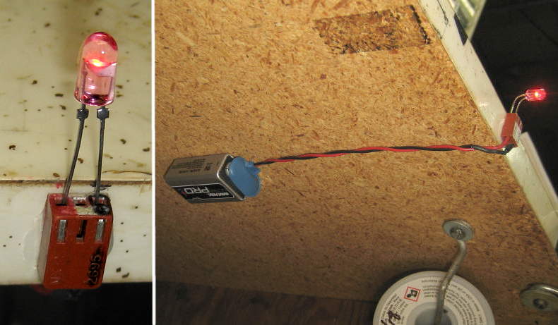 I couldn’t see the trace side of the display board, but I should be able to light the LED with wires from my edge-of-the-bench LED tester (old dead 9V battery – maybe 6V? – and maybe a 470 ohm resistor) without hurting anything.
Finding the LED leads
Using a continuity tester and then an ohmmeter, I found one ribbon pin connected to power supply minus. With the negative side of the LED tester on that, I watched the LED and brushed the + end of the tester lead against each other ribbon pin in turn. Nothing!
Very surprised, I moved to plan B. Maybe there’s an open collector driver and the LED is connected to +. I found a pin connected to V+ and tried that way. More nothing. Plan C: I’ll take the dumb thing apart and look at the traces.
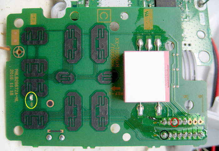 Murphy arranged for one of the screws securing the display board to be obscured by the main board, so that had to come off first. Two screws – not bad. Two more screws for the display board and I could look at what I had. I tried the LED tester leads directly on the pads of the tiny (0605?) LED – no light. Very surprising, but consistent with earlier observations. Using a loupe, continuity tester and ohmmeter, I finally chased the plus and minus leads of the LED (polarity marked on the board – thanks!) to two ribbon pins. Confident of that wiring, I soldered a pair to those pins, closed it all back up, reconnected the base to power and line, and called and left a message. The LED blinked, just like always. So far, so good.
First test: I hooked my dear old logic tester to the newly brought out LED leads. There was a faint flash of the Pulse LED, but the logic level showed always Low. Yeah, I suppose that’s OK – the forward voltage across the LED isn’t really a valid logic High. But still.
Brief aside on logic testers
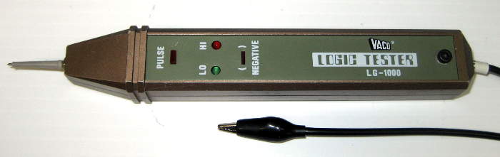 I can’t believe they don’t make something like this go-to device – battery powered, no power switch – any more. There are lots with 2 clip leads – presumably so power and threshold levels match the circuit under test – but for normal TTL or 3V or CMOS signals it’s so nice to just clip to ground and go! In searching over the years, I’ve found used ones on Ebay branded Sanwa and Soltec – clearly the same device – as well as Vaco. I don’t think I’ve even been able to find a schematic for making one. Seems like such a sensible device. But I guess I’m the only one who thinks that any more. 🙁 Yeah, yeah, I could design one. But I do still have this last working unit…
First noise
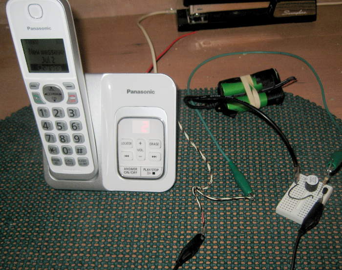 So I made up a simplest-possible proto that should beep on an LED forward voltage and hooked it up to the new LED leads. It beeped in time with the LED flashes. When I disconnected it, the LED got a little brighter, but only a little. Success!
Proof of concept DONE. Strangely, I feel a little less pressure now to actually do the implementation. Might just replicate what I did on a bit of perf board (using phone’s power) and stuff it inside. Downsides are more beeps than necessary, and no way to silence it. (Except, of course, listening to the messages.) Or I could put a Tiny85 on the board, listen for flashes, and do whatever more genteel beeps I chose. One could argue I should at least reconnect the little proto board and battery so if someone leaves a message before I get around to the final implementation, we’ll at least know about it. Fine.
Can’t stop myself. Clip leads were too ugly, so soldered 0.025″ pins to the LED leads, and to a 9V clip with an old “dead” 9V for power and wired it up. And the darn thing started to beep. WTH? Then I realized: There was an actual message on the machine from somebody – and we’d missed it because of the dumb LED-only alert! Pretty good for its first day/second on the job.
OK – let me listen to the message. Then I stumbled across a semi-fatal flaw: The Alert/Play LED remains on as you’re listening to the message. And so does the new beeper. In addition to my thinking it was annoying and made it hard to listen to the message, I could project with very high confidence that Lauren would think the same, only much louder. The attractiveness of putting a processor in the final version just went way up.
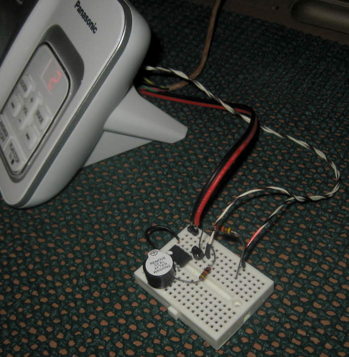
But what am I gonna do until then? I soldered a microswitch to a 7 position 0.1″ header for mechanical support and put its NC contacts in series with the battery. And I put a label on to 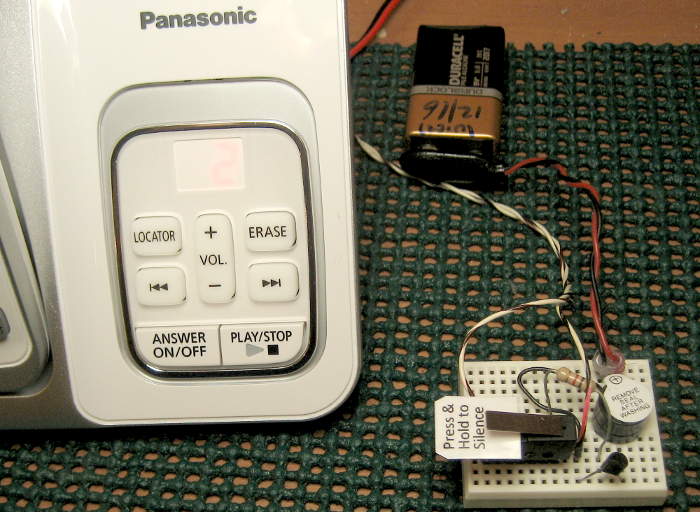 remind Laur (and me) to hold it to silence the beeper. But the layout was awkward with wires on top of the switch, etc. I ended up with the switch in series with the new LED leads, so at least it was near the front of the breadboard. Not a great solution, but it should work until I get around to a more proper software-based solution. Here’s the proto I hope will fly. Fortunately, we don’t get a lot of messages. 🙂
Update 7/10/18: The breadboard and microswitch got a fair amount of (mostly but not completely good-natured) flak about being ugly, but by promising that it was only temporary, it was allowed to stay.
We’ve come home to messages/beeping a couple of times since it was installed. Main goal accomplished! But the bit about continuous beeping as the message played hit home again. And its end-of-all-messages cycle takes an annoyingly long time until it finally shuts the LED (and noise) off. I guess the Tiny85 needs to only beep on flashing input signals. OK – it’s just code.
Update 8/6/18: To keep from draining the old 9V battery while we were gone for a week at Kirkwood, I unplugged the battery. Yeah, it wouldn’t be beeping like it was supposed to do when we got home, but surely I’d remember to hook it back up when we returned. A day or 2 after we got back, I noticed and remembered – and listened to the 2 messages the flashing LED was valiantly, if ineffectually trying to tell us about. Then I plugged the 9V back in and we’re back to <ugly but alerted>.
First ‘smart’ beeper
9/27/21: Partly inspired by Steve’s comment, I’ve made progress on making the dumb beep stop while you’re standing at the machine playing back a message. A Tiny85 listens to the LED voltage, and beeps only when the LED is flashing. That means it might miss the very first (or last?) flash/beep, but that doesn’t matter at all, since its real job is to be beeping when we come home.
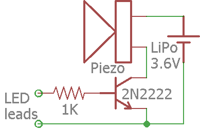
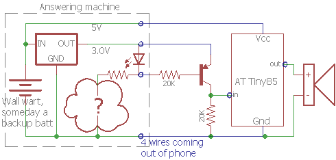 It was fortunate that I already had power supply leads coming out (for some future backup battery), so I already had all the connections I needed. After some voltage measurements and head scratching, I suspect there’s a 3V regulator inside after the 5.5V wall wart. Here’s what I’m guessing is inside, with my proposed next version.
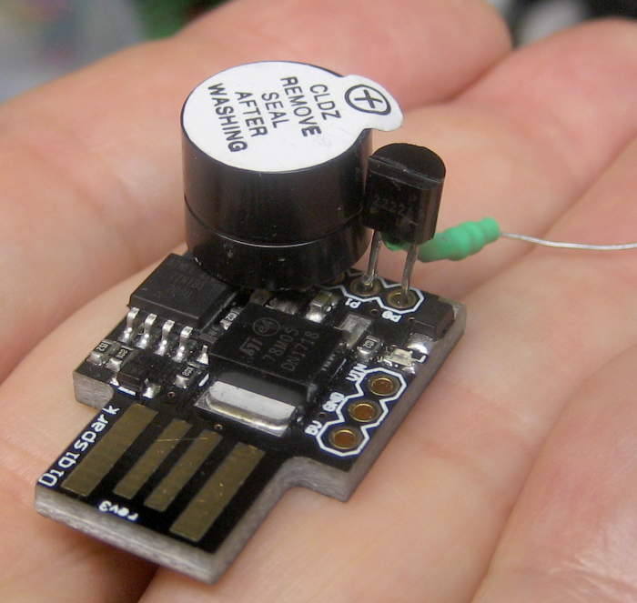 Since I’m out of the nice little general purpose Tiny85 PCBs from years ago, I made up a Digispark for the job. But then I worried about drawing too much current from the 3V regulator, so switched to a bare Tiny.
The datalogger showed the LED flashed very consistently 50% duty cycle with 620mS on and off. For testing, I wrote a simple simulator for that square wave on another Digispark.
I think the 15 lines of code for the actual beep controller worked first try. But after I set the clock prescaler to /32 to cut current consumption (it ran at ~1.5mA!) I had to tweak the timings considerably more than I expected to get it to work. I even had to drop back to /16 prescaler (still only 2mA) to get a little more precision on the timings.
 But it seems to work as designed. Yeah, it’s still on a breadboard on wires out the back of the phone. But there’s no longer a 9V battery, and no microswitch I have to hold down to stop the dumb beeping!
10/4/21: I just had the pleasure of walking up to the beeping machine to play a new recorded message. As soon as I pressed ‘Play’, the noise stopped – exactly as it should. The rest of the Play/Erase/whatever interaction continued without noise and without having to balance the stapler on the ‘shut up’ microswitch. Perfect! Well, except that it’s still all on a breadboard outside the case.
I went down a simar path. We would miss messages because we did not automatically look at the blinking light. I never did find the LED leads on my unit. They are embedded in SMT.
I finally bought a cheap photo sensor/relay trigger board on ebay and taped the sensor to the top of the phone (the part that flashes). That is hooked up to a beeper and wall wart supply. It’s in my den, but we can hear it when we walk into the house. It’s worked well for several years.
Panasonic really left out an important, easy to provide, feature!
Clever hack, Steve. But you must have to put up with the dumb noise during playback as well, no?
I really should get back on getting a processor to make it less annoying when playing messages. Thanks for the note and reminder of that, Steve!