
I’ve had an Aprilaire 600 humidifier on my furnace for several years, but only recently paid enough attention to notice that it was on all the time. It’s a dribble-water-down-an-aluminum-pad type, with whatever doesn’t get evaporated by the airflow being collected at the bottom and draining through the furnace drain.
The problem
Obviously, if the heat’s not on, not a lot of the water will evaporate, and most of it will just go down the drain. That’s what I wanted to fix. I only want it on when the heat/blower are on. Maybe the installer just hooked it up wrong?
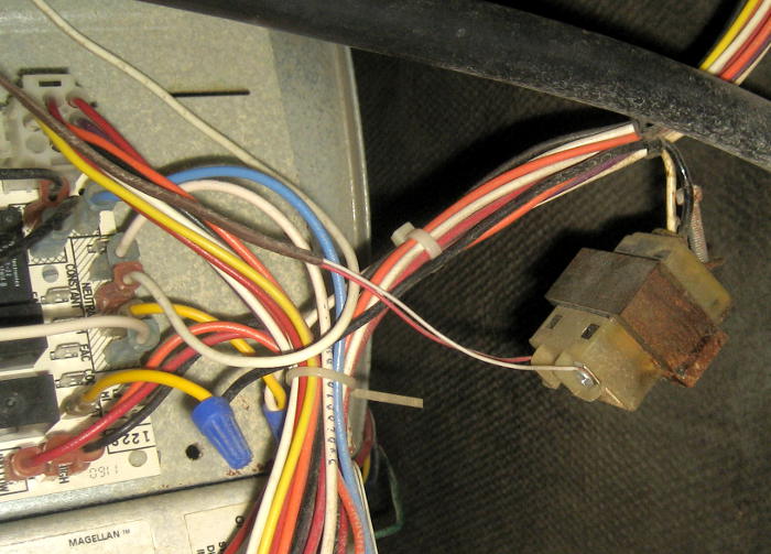 I took a look at it, and the installation is pretty half-assed with the transformer hanging by its leads. But the transformer primary goes to the HUM terminal on the ST9162 fan timer control board (and neutral), so it looks like it’s wired sensibly.
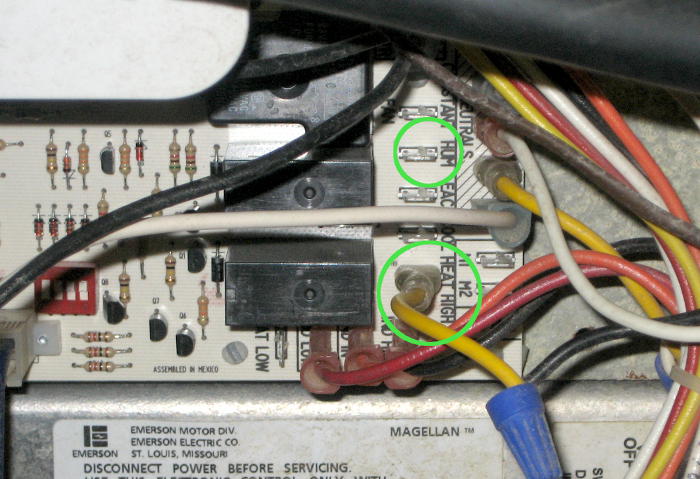
The manuals for both the furnace and the fan timer control board indicate the HUM terminal should be live only if the furnace is fired and the blower is on “heat speed” – which sounds just like what I want. Unfortunately, that’s not how it is behaving.
Part of the problem is that I have the fan on continuously to circulate air in the house. The variable speed DC blower motor runs the fan fairly slowly all the time, and kicks it up to circulate more air when the burner is fired. (I think it goes even faster when stage 2 heat is called for.) If I leave the fan in “Auto” mode – only on when the furnace is fired – the humidifier comes on appropriately. It’s when the fan is in the ON mode that the humidifier is always on.
The first hack
The fan timer board will control either a variable speed DC motor like I have (via an external blower control box) or a multi-speed PSC (Permanent Split Capacitor) AC blower motor. Maybe I could just connect the humidifier transformer to the unused PSC motor terminals. (Yeah, despite the Aprilaire manual saying “IMPORTANT: DO NOT WIRE TRANSFORMER INTO FURNACE BLOWER CIRCUIT.” But they don’t say why, so it must not be that important.)
I brought leads from HEAT LOW and HEAT HIGH terminals outside the furnace, closed the furnace back up, and looked at them with a voltmeter under various conditions. It looked like the HEAT HIGH terminal went active when I wanted. Now the manual shows that this terminal goes straight to the PSC motor, supplying run current. Surely it can handle the humidifier transformer. (Full disclosure: The other end of the voltmeter was to ground, not neutral. Surely that can’t matter…)
 So I moved the transformer input from HUM to HEAT HIGH, closed up the furnace, and thought I’d be home free. But no. It didn’t ever really seem to come on. (Later observations with that configuration made it look like it might have come on briefly when heat was called for, but didn’t stay on during the heating/blower cycle.)
 Back in the furnace air handler cabinet – this time with the interlock cheater in place. The PSC terminals continued to be weird. If I just touched a voltmeter lead to the HEAT LOW terminal (with the other lead to neutral) when that terminal was hot (which was when the blower was at low/circulate speed), the furnace would shut down for several seconds. Fortunately, it then restarted. When I put a meter lead on the HEAT HIGH terminal when that was high (which was when the blower was up to normal heat speed because the furnace was fired), the blower would speed up – perhaps to stage 2 heat/high fire speed?
Both those reactions to a meter lead are a complete mystery. How can a terminal expecting to provide 120V run current to a blower motor even detect that there’s a voltmeter lead connected to it? OK, the fan timer board clearly knows it’s running a DC motor, so I suppose it could alter its behavior on the PSC terminals. That still doesn’t explain why.
The PSC terminals were still able to supply some current. I tested with a 10W light bulb, and during some observations saw HEAT HIGH actually run the humidifier’s 24V water solenoid. I’m really baffled.
Second hack
OK, that didn’t work. (Though I haven’t a clue why not or what it was actually doing.) How can I control 120VAC to a transformer to the humidifier when the furnace is heating/blowing?
Well, how about W1 from the thermostat? That provides 24VAC when the thermostat is calling for heat. That’s almost exactly when I want the humidifier on. (Yeah, it would be on for the minute or two after initial call for heat while the inducer spins up, the burner fires, and it gets hot enough to actually run the blower up to heat speed, and it would turn off before the post-call-for-heat fan delay sucks the last heat from the heat exchanger. But I can live with that.)
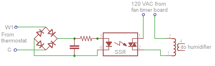 I could use one of my cheap opto-coupled solid state relays to control power (from HUM or a CONTINUOUS terminal) to the transformer. If I ran a full wave bridge and a cap, that should power the SSR’s input LED OK. Maybe a series resistor would decrease the peak LED current and let me use a smaller cap.
Circuit design
The relay I grabbed needed 1.95V and 3.5mA to its LED to just switch on reliably (both half cycles). Additional points of reference are that it drew 14.5mA with 24VDC across its terminals and 2.24V at 5mA. The 5mA should be a good minimal but conservative current.
I tried it out, and it looks like it would work OK with a 10uF cap and 2200 ohms in series. And while that would probably draw not unreasonable current in steady state, I’m really uncomfortable with initial inrush current with a 10uF cap straight across the (diodes from the) thermostat leads. I’m still struggling with that. Seems like a smarter circuit should be able to give me 5mA without a huge inrush.
OK – new design. How about a nice series resistor to limit inrush, and a more efficient circuit to discharge the cap slower? A current regulator should give me a nice constant 5mA and let the 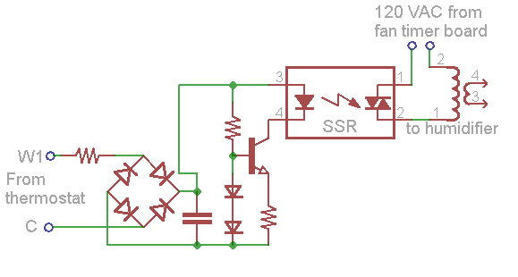 filter cap survive despite the input resistor. The classic quick and dirty constant current sink is a transistor with its base 2 diode drops above ground and an emitter resistor that raises the emitter to 0.7V at the desired current.
Hmm – but in order to get pretty constant voltage across the diodes we need some current thru them. Say 5mA should do it. But that doubles the current draw of the circuit that I’m trying to make efficient! Boo.
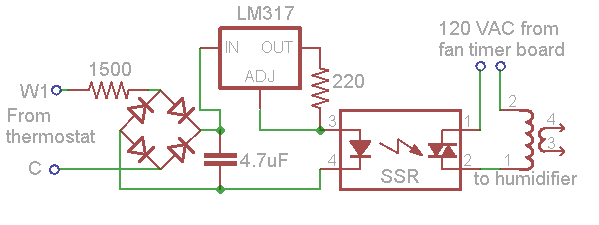 OK, how about an LM317 and a resistor as a current source? If we need 1.25V across the resistor and want 5mA, R should be ~250 ohms. If we make it 220, that provides a slightly more conservative 5.7mA (at which the voltage across the SSR input is 2.73V).
If we need to supply 6mA, let’s limit the max current to say 20mA. The cap should charge up in a few cycles and we should get good DC out. Yeah, the transformer will bounce a few cycles with a less than full-ON LED, but I’m guessing that won’t hurt anybody. On 24VAC, our full wave bridge should give a peak of ~33V. If the current regulator and SSR LED drop 1.25+2.37+1.5=5.1V, we have ~28V peak trying to charge the cap. (That 1.5V is 317 dropout at low current.) WRONG – we have 33V trying to charge the cap if it turns on at the peak of a cycle. To limit the current to 20mA, we need ~1400 ohms in series with the rectifier. Let’s call it 1500. 6mA will go to the LED, but all that does is charge the filter cap a little slower.
So how big does the filter cap need to be so discharging it at constant 6mA will never drop it below 5.1V? Google found this nice reference which shows the linearly decreasing voltage on a cap with constant current drain as V=Vmax-(it/C). Allowing 33-5=28V of drop, we get it/C=28. At 6mA for say 0.01sec (conservative for 1/120 sec), the formula says we should be good with ~2 uF. So for an SSR, a 317, a 1500 ohm resistor and a couple of uF, I should be able to turn the humidifier transformer on reliably and never draw more than 20mA from W1! (That was more arithmetic than I’ve done for a circuit in quite a while.) I suppose if one were thinking too hard about all this, one could describe it as a sort of digital 24VAC current amp. We draw 20mA from the thermostat, and provide probably quite a bit more to the humidifier and its solenoid. <goes off to breadboard circuit>
Success
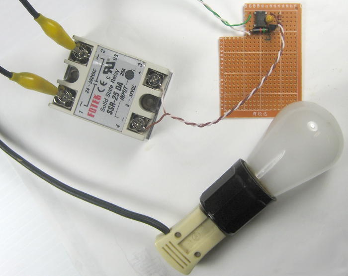
 It works! The 10W bulb the SSR is driving on the bench comes on solid at ~19VAC into the bridge rectifier. And (reassuringly) the visible DC indicator LED in the SSR doesn’t change brightness as I crank the AC input voltage up. I didn’t have a suitable 2uF cap, so I used 4.7uF. Should be fine. I guess it’s time to house it in a manner suitable for mounting inside a furnace that I don’t want to start the house on fire.
<whine> Housing and mounting the parts was a lot of darn trouble. I needed spacers to mount the little perfboard circuit, but the nice plastic 1/4″ long ones I had were too long. I had ground the required two down to the right length on the belt sander, but while trimming the excess, dropped one into the big waste basket – where it remains unfound. The next one caught in the sander belt, got ripped out of my hand, and is probably still buried somewhere inside the sander. After that, I tried to cut the next one down instead of sanding, but broke it in the process.  The fifth one made it. I didn’t have the right length 6-32 screws to mount the SSR and the perfboard so I had to cut long ones down. The unusual mount for the transformer required an asymmetric
 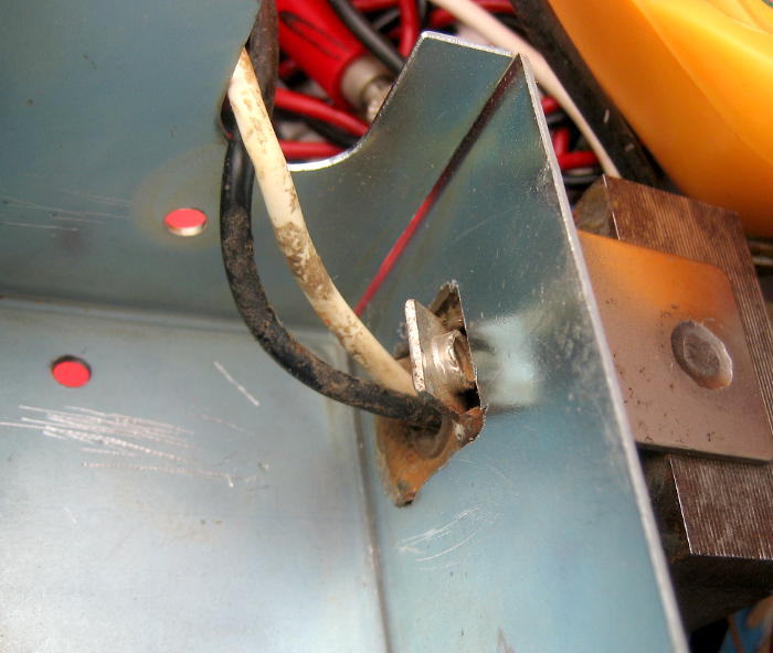 hand-trimmed cardboard template to get the shape right, tracing the shape on the steel box, and the never-fun drilling a bunch of holes, breaking the center out and filing until it was the right shape. I did all that – and then realized I’d traced it upside down so it would be impossible to tighten the mounting screw! Fortunately, I was able to re-file the asymmetric shape on the other end of the hole and get it fit in the right way. And of course the 120V leads needed wire I don’t stock, and when I found some, it had to have connectors crimped and heat-shrinked. Yes, I have the ability to do every one of those steps, but it just seemed like I had to hand make and hand fit every darn piece. </whine>
Final product
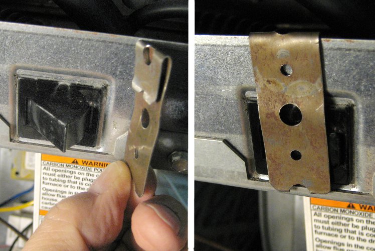
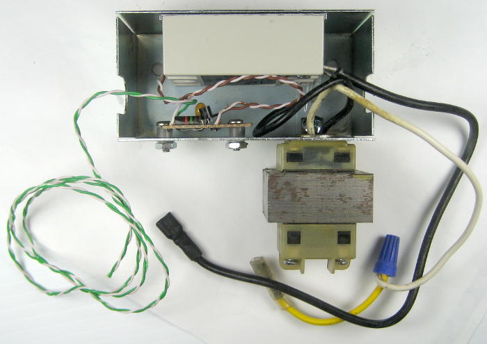 I found a steel box to house the parts, and got everything inside. I’d never seen a mounting like the transformer had, but after I cut
 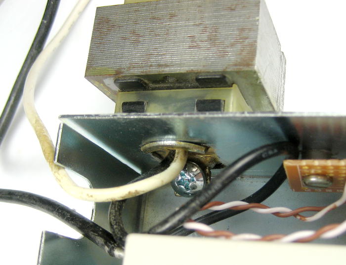 a suitable hole, it mounted securely. I found some small spiral-cut wire protector stuff and made the solid green/white Cat5 pair going to the thermostat screws a little more robust.
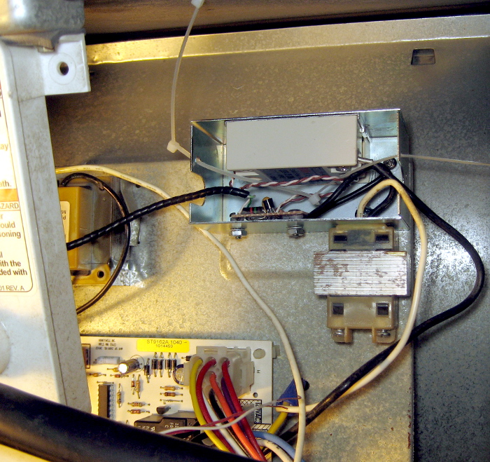 Here’s the box mounted in the furnace (complete with the zip ties that will hold the top on). When I closed it all up and turned the furnace back on, after a few seconds the usual relay clicks sounded, but the blower didn’t come on. Damn. I opened it back up, rechecked everything, wiggled wires, and finally pulled the 120VAC wires to the new control and closed it back up. Still no blower. But as I waited a little longer, the inducer spun up and the burner fired. That was going to be bad without a fan! I shut it off.
I opened it up again, convinced myself I hadn’t screwed anything up, reconnected the 120V leads, closed it back up and turned it on again. I figured there should be an override that would shut it down if the heat exchanger got too hot with no fan, and I was standing right there to watch it. Still no constant blower. 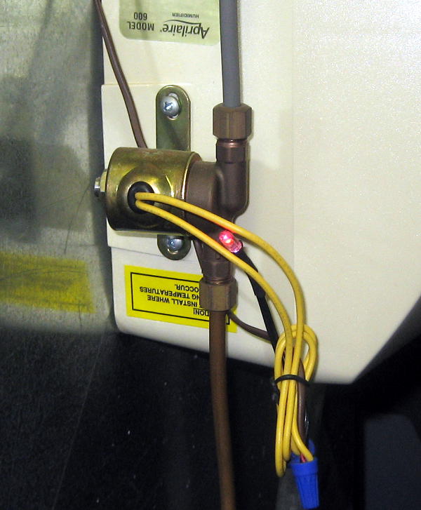 Inducer spun up, and the burner fired. And then – the blower came on to heat speed! That was very reassuring. I looked at the LED I’d recently added to the humidifier solenoid, and it was on – just like it should be. I waited for the call for heat to end, and glory be! – the blower reverted to low circulate speed! And the humidifier LED was off. I watched through a couple more cycles, and it looks like everything is finally working as it should.
Well, that was a lot of trouble for what I think should have worked right in the first place. But it’s done, I feel pretty good about the parts and construction, and the humidity in the house is coming up!
Pingback: Aprilaire 600 runs continuously - DoItYourself.com Community Forums
My windows started fogging yesterday when the temp dropped to 10 degrees. I was thinking about building a wifi humidistat that would get the forecast low temp and choose the humidity level based on that? what do you think?
Hi Ed,
Sure, using weather forecasts to tweak your HVAC system can work. I wrote a little perl to parse some text weather forecast and send me an email every evening so I could decide, based on the temperature, dewpoint and tomorrow’s likely high, whether to turn the whole house fan on. Typical message:
Friday: Showers, mainly after 1pm. High near 68. Southeast wind 10 to 15 mph, with gusts as high as 20 mph. Chance of precipitation is 80%. New precipitation amounts between a tenth and quarter of an inch possible.
temp: 47.1 dewpoint: 44 1 seconds old from KILLOMBA4
As soon as I have a good external humidity sensor, I’ll know the dew point, though tomorrow’s high will still be useful.
For your application, though, hardware solutions exist. I also had problems with condensation when outside temps were very low. My AprilAire model 56 duct mounted humidistat has the facility to add an outdoor temperature sensor for just this case, so I bit the bullet, bought the overpriced sensor, mounted it outside, and wired it in. The wiring includes 24VAC in (from the post above!), a pair to the humidifier solenoid, and a pair from the OutDoor Temperature sensor. Maybe not perfect, but it allows the ‘stat to lower humidity when it’s very cold out without my having to do anything.
Good luck!
Jim
