The furnace failed to fire up the other day when I tried it for the first time this season. I learned a fair amount about its components and how they work as I tried to figure out what was wrong and fix it (which I did). This note is just to record most of what I found out to put it in one place and so maybe I can do it more easily next time.
Furnace background
The furnace is a high efficiency Kenmore H9MPV100J20B1, installed 9/05. It has a variable speed direct drive DC blower motor, which is quieter and allows easier constant low speed air circulation. I have a nagging suspicion the 14×20″ filter is too small but the installer was too lazy to reconfigure for a larger one.
Control is distributed among 4 devices:
- The programmable smart thermostat sends requests for heat, cool, fan according to a schedule to the rest of furnace (via its interface module).
- The Fan Timer Control board controls the main blower, with features like keeping the blower running for several minutes after call for heat is over, optional continuous slow air circulation, etc. It listens to the thermostat, and sends requests to the Smart Gas Valve (for heat), to the A/C for cool, and to the blower controller.
- The Smart Gas Valve controls everything about the heating burners, with lots of safety interlocks. It gets requests from the Fan Timer Board. Its LED flashes a heartbeat or troubleshooting codes.
- The Blower Controller gets requests from the Fan Timer board and controls the DC blower motor.
I upgraded the originally installed Honeywell TH6110D programmable thermostat (which is probably still around somewhere) to a Honeywell VisionPRO IAQ around 9/07. I think a main benefit was a humidity sensor so it could deal with coolish but humid nights that were uncomfortable at a normal A/C thermostat’s fixed temperature set point. (It goes for a few degrees below the set point if humidity is above a threshold.) This touchscreen in the kitchen gets its 24VAC and communicates over 3 wires to an interface module mounted near the furnace. That device provides the usual 24VAC signals for fan, heat, and cooling.
Basic output from the interface module is the usual 24 VAC signals:
– W1 call for heat
– W2 call for stage 2 heat
– G call for fan
– Y call for cool
– R 24VAC power to thermostat
– C common
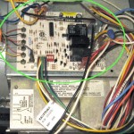 These all come into a Honeywell ST9162A 1040 “Fan Timer Control” board which lives in the lower air handler compartment of the furnace (green highlight). That board can control either a PSC (permanent-split capacitor) AC blower motor directly or a variable speed DC motor via a separate motor controller (large box below the Fan Timer in this furnace) as it does here. You can see the 6 conductor motor control cable from the lower left of the Fan Timer. I think that’s mostly 24VAC signals, but I’m not certain. The 24V transformer that provides power to all the controls is above and to the left of the Fan Timer board.
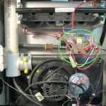 Control of gas to the burner is done by a Honeywell SV9541 “Smart Gas Valve” living in the upper burner compartment of the furnace (green). It’s pretty slick, integrating all burner control stuff: main gas valve (with low and high rates), the igniter, gas to the pilot light flame, the pilot flame sensor, the draft inducer fan (routed via the FT board), various pressure sensor switches, and even an LED to provide coded flashes for troubleshooting. I hope it never goes out, because as near as I can tell the installer took shortcuts that will almost require disassembling the whole furnace to replace it. (OK, maybe you just cut the pipes. Cutting gas pipes is probably a special process.)
Troubleshooting this problem
It was getting chilly, and I’d touched the thermostat to go to heating mode, but there was no heat. There’s nothing that has to be turned on when heating season starts, so I started to investigate.
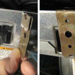 The first obstacle to troubleshooting was an interlock switch on the door to the air handler compartment that turns everything off when the door is open. Yeah, I could have just
 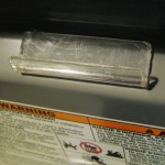 taped it, but I made up a little cheater out of pipe strap. I soon found myself grumbling about trying to pull the air handler door open against air pressure while it was running, so I glued a little plastic finger grip on. Works fine.
Surprisingly, I couldn’t find the paper manuals, but furnace, fan timer board and smart valve manuals were readily available online, so I now have a nice set of .pdfs. The obvious first check was for 24V on W1 from the thermostat. (Well, first was to reacquaint myself with the fact that the thermostat in the kitchen doesn’t control any 24V signals – just sends digital info to a the IAQ Interface module down by the furnace.) Yes, we have call for heat.
So how does this Smart Valve thing work? The diagnostic LED constantly blinked bright/dim – a heartbeat indicating no problems. Was it really not getting call for heat? The diagrams show a wire called “data” into the valve apparently to call for heat. “Data” is a troubling name for a 24V signal. But I found a diagram about how to use the SV with an old style 24V thermostat, and it was obvious that it was OK to drive the data wire with 24V. So do I have 24V?
Pulling the 8 pin connector to the SV so I could put a meter on the pin might not be a fair test, as I didn’t know what other interlocks there might be. I stuck a thin piece of wire into the back of the connector (while it was still connected) and measured the voltage: 14 VAC. Not one of the expected values. But clearly not the 24V (actually 27V) I was seeing other places.
I wanted to put 24V on that pin to see if it would at least start the inducer fan or give some evidence of trying to work. But I didn’t know what the output circuitry of the Fan Timer (which provides the signal) was, so just driving the pin with 24V while it was still connected to the FT wasn’t a conservative thing to do. To remove the male pin from the 9-way Molex connector on the FT, I manufactured a little pin extractor out of a female Molex pin. With the orange “data” wire out of the connector I was free to put 24V on it. The connector geometry was conveniently such that I could force that loose pin into the back of the connector at a pin with 24 V and it would make contact and stay there. I did so – and the heat came on!
It was now pretty chilly in the house, and Lauren was coming down with something and a cold house really wasn’t good for her, so I decided to let the house heat up for a while.
It did, but not very fast. And I didn’t hear the blower as loud as usual when the heat is on. I’m not sure what was happening. One possibility is that the FT never kicked the blower up from the constant low air circulating speed to “heat” speed. Another is that it usually goes to stage 2 heat (high fire) with the attendant higher blower speed and those two steps didn’t occur. I don’t think the SV has a W1/W2 input concept – just put 24V on the data line to call for heat. But it does monitor other pressure sensors. Maybe the “high” pressure sensor detects higher duct pressure from high fan speed and that’s how the SV decides to kick up the gas rate. In that case, it’s the FT cranking the blower up to high that makes the burner crank up to stage 2.
In any event, if the FT wouldn’t send call for heat on the data line, it’s plausible that it wouldn’t kick the fan up either. And perhaps not even for a W2 stage 2 heat request (which was in fact present). That board is looking more and more like a problem.
I should check the furnace supply side temperature data history in the house monitoring system. If the fan never went to stage 1 heat speed, the duct temp should have been noticeably higher than usual.
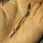
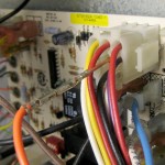 I wanted to see what the FT was putting out when wasn’t connected to that pesky 14V from the SV. I cobbled together a pin extender out of a male and a female Molex pin with an inch or so of #14 solid between them. I could insert the male (with its latching dogs defeated so I could get it back out easily) into the connector to measure the FT side and orange wire separately, and put the orange wire into the female comfortably outside the connector to reconnect them. By the time the picture on the left was taken the female had broken off. But it held long enough to do the test I needed. Sure enough, the voltage on the wire didn’t change when call for heat was on. Another strike on the FT board.
I couldn’t find a schematic for the FT board, so I started to trace the wiring to find whether the 24V in on W1 went all the way through to the “data” wire out. The path wasn’t obvious. The board was mounted on 4 nice little plastic board standoffs, so was easy to detach. It’s single sided, so tracing would be possible. I took closeups of both sides of the board (3 for each side) so I could clearly see resistor values and all the traces. I didn’t end up reverse engineering a schematic out of them, but the pics did come in handy later.
The repair
It looked a lot like the FT board was bad, though I didn’t understand all the interactions/interlocks well enough to be certain there was nothing else wrong. Let’s replace the board. The furnace manual showed the part number – 1014459 – so I went to the Sears parts direct web site. I found the part – but with a notation to the effect that the manufacturer would not allow them to sell the part! WTH? I called during business hours and got confirmation that they couldn’t sell it, but not much insight into why.
A quick web check found the boards for $125-$250. (I did find one page on the Sears site that showed a price of $78.) OK, I can get them, though I’d rather not wait a couple of days. This is just a replaceable furnace part – surely I can get one at a HVAC parts place locally. I probably called 10 places, and nobody had one and would sell it to me! I did get a little more insight into the refusal though: furnace repair should be done by a licensed furnace guy, not a home handyman. C’mon, it’s just a circuit board, not a gas valve!
Finally the last place I called (yeah, yeah) had the part and grudgingly would sell it to me. They were only supposed to deal with licensed contractors, but times were kind of tough, so they’d bend the rules a little. I paid $179 (plus tax), though the guy made a big point of showing me that the real price was $255. Thank you. Whatever. It appeared to be exactly the same as the one in the furnace.
I got the board home and started moving the wires one by one. You wouldn’t think that would be very hard, but I managed to make two mistakes. I pulled one of the later wires but noticed only approximately where it came from (one of two places). Fortunately, I had the pictures I’d taken earlier, and could see its original home clearly. The other was worse, and I didn’t find it until it was all back in and I turned it on. Nothing. Nada. Not even any hum from the annoyingly loud 24V transformer. Not good. I checked the breaker, and it was tripped. Damn.
I found the blue 120V-in wire, and I’d put it on one terminal off. (OK, and the pins were oriented 90° off.) Unfortunately, the pin I’d put it on was one of the block of neutrals. Ouch. At least that would explain a tripped breaker. I moved the wire to where it was supposed to go, turned the furnace on, and everything worked fine. My educated gamble in replacing the board paid off!
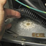 I cleaned up, put the “data” pin back into its Molex connector and was buttoning things back up when I noticed a deposit of crud that pretty clearly came from drips from the flue pipe. Looks like it’s a sizable drip, or at least has been dripping for quite a while. This pic will at least give me a reference point to see if it continues to get worse.
Overall a successful repair, and I’m sure I saved a couple of hundred bucks. And learned a lot about how the furnace controls work!
I was a little surprised that the failure wasn’t the most predictable igniter/flame sensor. But the spare for that repair is still sitting reassuringly on top of the furnace.

Jim, any chance you can send me some pics of the wiring for the board?
Sure, I’ll be glad to share what ever I have. Exactly what are you looking for?
Jim,
Thanks for the post. I think I have come across your site for other stuff in the past (ATtiny or other) but just wanted to thank you for taking the time to post this material. I am working with a furnace issue with SV9541 so this post came up on a google search.
Thanks, Mark. I hope it helped. Good luck getting your heat back!
Jim