
The fact that my attempts to fool the charger into pushing more energy into the battery resulted in no significant gain in capacity is a fair indication that the charger isn’t at fault, but I wanted to make sure.
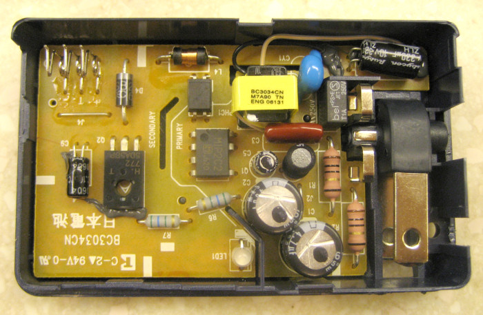
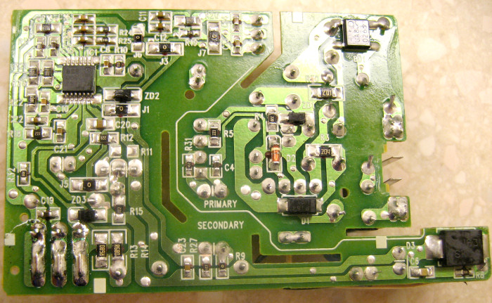
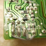
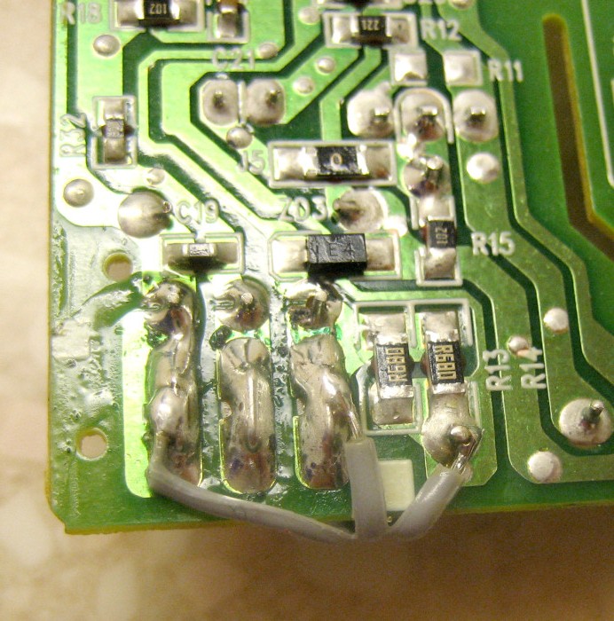
After some ugly marks on the case, I got the charger open. You can see the slick folding AC plug and the wire battery contacts (top left) in the first pic. The wire contacts are in the bottom left of the back of the PCB (2nd picture) – we’ll need those!
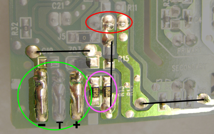
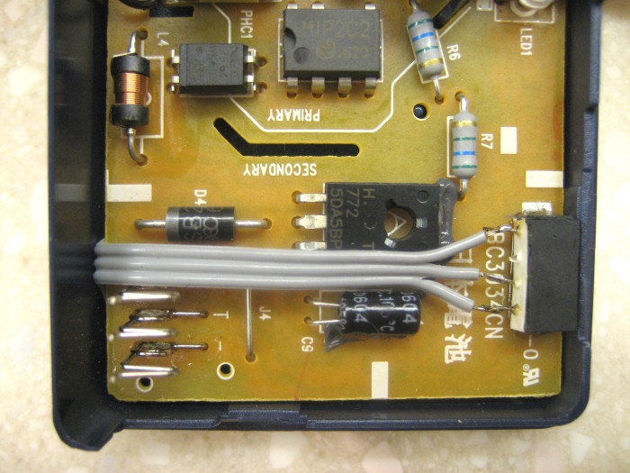
What I need access to is the + and – terminals, and ideally some way to measure the current. Expecting that to handle the rated 0.65A of charging current the traces would have to be quite wide, I located the high current paths on the board. In the third pic, the terminals are circled in green (middle one is a temperature monitor we don’t care about) and the series pass power transistor is in red. The black lines are essentially jumpers on the other side of the board. Power comes in from the right somehow.
Of great interest are the two paralleled 0.68 Ω resistors circled in pink. (We recall that SMD resistors use an “R” for the decimal point, so they’re not 68 Ω.) They’re in series with the + side from the transistor. We have our current sense resistors! Now I just need connection to +, -, and the bottom of those resistors.
-
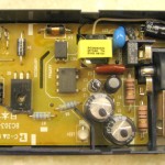
- Charger open
-
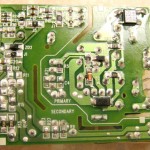
- Back of PCB
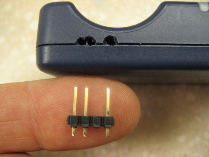
Having blown too many things up, I’ll use a polarized connector. I need three pins – I’ll use a four pin 0.1″ female header. There’s room for it across from the battery terminals. I used some ribbon cable for the wires, and soldered them to the appropriate places (1st pic). I epoxied the female header to the board, carefully marked where I needed holes, and made a connector.
-
- New wires soldered
-
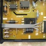
- New connector in place
-
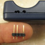
- Connector & connectee
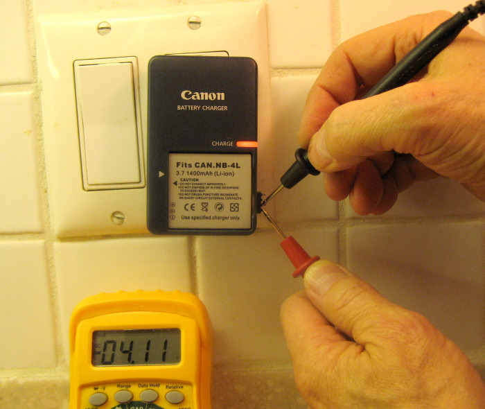
I put it back together, started charging a battery, and was able to measure the terminal voltage without even using tin foil!
-
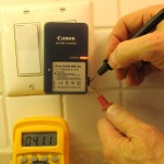
- No more tin foil!
Next step is to make an accurate DC amplifier to use with the series resistors to monitor current. At the rated peak of 0.65A and 0.34 Ω, the highest voltage I should see is around 0.2V. With a gain of 20, I would have a nice 4V signal – very compatible with the 0-5V analog input range of an Arduino. And the terminal voltage – maxing out at a little over 4V – is also right in range. Then I can have the Arduino monitor voltage and current as I charge a battery and verify whether the charging curves look like (I think) they should.
(My guess – to be hermetically sealed in a mayonnaise jar under the porch until all the results are in – is that:
- The charger is fine.
- The original few-year-old Canon battery is really down to 0.3 Ahr, a victim of normal aging.
- All the other cheapies are junk. )
More to follow…