
 I got the cute little 8 pin Atmel AT Tiny85 working with the Arduino IDE by following steps and hints in this post and playing with a couple of different core libraries.
At under $3 each, this chip is a great way to provide a little programmable control for a project where an Arduino might be overkill. If you use the internal oscillator, you can get five or even six I/O pins. In addition to normal digital I/O, it provides up to 3 analog inputs and 2 PWM outputs. There are limitations (including no easy serial) but you can do a lot with it.
You can write and debug code on an Arduino, change pin definitions to fit the 8 pins on the Tiny, then download it to the little guy. There’s no bootloader, so you need some kind of programmer to get the code into the Tiny. Fortunately, the “Arduino ISP” sketch included with the Arduino development environment is just the programmer we need. A couple of wires connecting the Arduino to the Tiny (usually on a breadboard) and we’re ready to go. The details are in the post from hi-low tech above.
One detail not correctly stated on the HLT page is that for Duemilanove you need to block the Reset signal (carried in on the DTR pin in the serial interface from the IDE) to keep it from interfering with programming the Tiny. The 10uF cap from the Arduino Reset pin to ground prescribed for the Uno works fine.
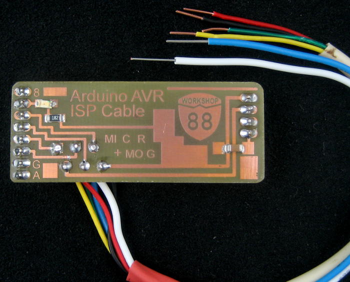
 While wires stuck into the female headers in the Arduino work fine, since I expect to use Tinys in a number of projects, I made a sort of mini-shield to make it easier to set up and to avoid the errors I’m sure to make. I also put the 10uF cap on the little board so there’s one fewer thing to remember. Labels for which wire goes to which Tiny pin keep me from having to look it up each time I use a Tiny.
I hope to share what I’ve learned in a class at Workshop 88 on using the Tiny 85 with Arduino. Since the boards are so small, I’ll just make some up and let the students solder the header pins and wires from the cable to the board and have a programming cable take-away.
Update 11/27/11: Since I’m going to be using this cable (and an Arduino) as a programmer for other projects including one with five Tiny4313s, I redid the board to be convenient to use a ribbon cable to the “standard” 6 pin ISP header on the Arduino. It looks like many of the AVR family do serial in-system programming via SPI – using MOSI, MISO, and SCK (and Gnd) – and using the Reset pin to put the device into serial programming mode. It’s usually handy to have +5V, so those are the 6 pins on the standard header. This cable should be useful for several AVR chips – including burning bootloaders to ATMega 328s for Arduinos!
 The new mini shield is set up for comfortably hand-soldering a ribbon cable to it, with an insulation displacement female 2×3 connector on the other end. (Yeah, the one in the picture is a 2×5. It was midnight and that was all I had – sorry.) There’s even a cryptic legend showing which wires are MOSI, MISO, SCK, Reset, V+, and Ground (replacing the Tiny85 pin numbers).
I did a quick test with a modified Blink sketch and was able to program a second Arduino (without using its bootloader) from one with the shield/cable plugged on and Arduino ISP running. (There was initial confusion when the first/programmer Arduino’s LED blinked in addition to the second/target’s LED. But since SCK/PB5/Pin19/D13 is connected to the LED on all Arduinos, and since the programming cable connects SCK to SCK (as well as MISO to MISO and MOSI to MOSI), D13 on the second Arduino was driving the LED on _both_ Arduinos. D’oh!) Also, by modifying boards.txt based on this info, I was able to create a new “board” entry for Duemilanove using Arduino ISP.
Based on the Tiny2313 board profile that came with whatever core libs I’m using (I’ll figure out which ones Real Soon Now!) I should be able to create a 4313 profile with the larger memory sizes, the 16MHz crystals I’ll be using and set up to use Arduino ISP. With a little luck and if I can just keep from making any dumb layout mistakes putting that header on the 4313 boards, I should be able to program the 4313s!
I’ll post the Eagle files as soon as I can figure out how to use Github. Thanks for the suggestion, Dave!
Update 12/16/11: Just an update on usage of the cable and ArduinoISP: I had used the cable to burn the blink sketch into my “good” Duemilanove (leading to the success comment above), and it appeared to work fine. But the next time I tried to use that board, the IDE couldn’t talk to it – giving an avrdude out of sync error I really wish I’d captured. What I believe happened is that while it burned the code to the board, it overwrote the bootloader.
Since I had the cable and a spare Arduino (a Diavolino), I thought it would be easy enough to burn a new bootloader to my Duemilanove, presumably fixing it. I ran into problems I should have anticipated, but will help me remember for next time: I’d been using the Diavolino as an ISP (for some 4313s), but I wasn’t certain of its state, so I figured I’d just reburn the ArduinoISP sketch to it for good measure. That didn’t work – another avrdude out of sync error. Have I really blown the bootloader on both my Arduinos?
No. The Diavolino still had the cable mini-shield attached. That, of course, contains the 10uF cap that defeats the IDE’s resetting the board after a download, which interfered with downloading the ArduinoISP sketch. I removed the shield, and burned ArduinoISP with no problem. Then I put the shield back on, connected the other end of the cable to the Duemilanove, and burned the bootloader to it with no problem. After that I could talk to the Duemilanove from the IDE, which is what makes me think I overwrote the bootloader in the first place.
Takeaways:
– Burning a sketch to an Arduino through the ICSP with the cable works, but will overwrite the bootloader. There’s probably a way to set a load offset to avoid that, but I don’t know what it is (at least not yet).
– Trying to burn a sketch (ArduinoISP, and presumably anything else) to a board with the cable/shield on it won’t work. Take the shield off first.
Update 4/19/14: These mini-shields/cables have been a good success. We used 4 of them for code burning stations for the Thotcon badges, and I’ve handed them out at all the Tiny85 classes I’ve done. There are 2 upgraded versions.
 This is what I handed out at the most recent class. It’s just the same with the addition of one LED (and resistor) on pin 9 for the heartbeat. I didn’t even know about the LEDs until I happened to be looking thru the Arduino ISP sketch one day. The heartbeat LED is the most useful: if it’s “breathing”, the ISP sketch is loaded and running.
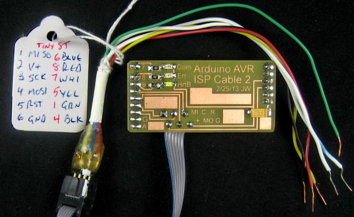 The one at the right is my “good” mini-shield, and is the one I routinely use (if I can find it). It has all 3 LEDs, and the ideal cabling arrangement: There’s a ribbon with a 6 pin 0.1″ female coming off the board so it can be plugged directly into anything (like an Arduino with a bad bootloader) that has a 6 pin AVR ICSP header. But there’s also a cable with a 6 pin male that plugs into the ribbon, but provides breadboard-friendly ends for when those are needed. The tag even shows the color/pinout for a Tiny85. Now that I’ve played with it, the 3 LEDs are overkill, and I think this is the only one I’ve made up that way. (Several students have opted to put a ribbon and a 6 pin female on, though.)
Hi Jim. Did you use the hw profiles linked from that site? I seem to remember I found another set somewhere that had more options when I was working on the blind closer. One of the two had clock issues too that needed to be edited manually for the internal oscillator, which was a real pain at the time with the pwm servo control. :/
Ugh. I’m not certain which core libraries I ended up with – which is why I didn’t put that info in. I think I started with the ones linked on the HLT page and ended up with others. I seem to have “hardware” and “hardware-other” subdirectories under my Arduino directory. I’ll dig through figure out what I ended with and post it here.
My main hack in the libraries was because I needed access to both the 2.56 and 1.1V internal references. I think I achieved that goal. Seems to me I had some battle with clocks that needed a manual edit as well, tho I don’t remember the details.
I would have had to dig out all those details anyway in order to do the class, but thanks for keeping me honest!
I’m about to have to go thru the select-and-import-more-core-libs dance again to provide an environment for Tiny 4313. (I needed a real UART and was going to use a 2313, but found the 4313 is just the same, but with double the flash, RAM, and EEPROM.) I think the SPI ISP programming is the same as for the 45/85, so I should be able to use my new shield/cable. I’ll add something here about that after I get the new chips and verify it.
Thanks Jim, I didn’t mean to grill you on it… I was just curious since I wrestled with it once before and meant to pick up a bunch more of the 85’s for future stuff.
I’ll be interested in what you dig up on the 4313. I have a 2313 here that I’d originally intended to use in the blind closer project until it turned out it didn’t have something I needed… though I can’t remember what it was.
Will you be sharing the eagle or fritzing files for that board?
Pingback: RF starter’s gun | Jim's Projects
Hi Jim,
Would you be willing to share the schematic for your board? I’m thinking of building a derivative of this board. We used the board that you (or someone at Workshop 88) sent to Derek to make the Noise-o-Trons at Pumping Station: One’s booth at the maker faires.
Thanks.
Hi Justin,
You’re welcome to the Eagle files of what I have. There have been a couple of versions of that board. The fanciest is IspCableShield3.sch|brd. That has all 3 LEDs, but requires connection to Arduino pin D7, which makes the whole thing bigger. Probably best is ArduinoIspCable2A.sch|brd. That only has the heartbeat LED, but that’s usually enough. There’s really nothing on the board except a 10uF cap to defeat the auto-reset. The pads for that cap accept either a 1206 or some larger cap I happened to have around. All the LEDs and their resistors are 1206.
Unfortunately, there are a couple of components from (poorly managed) private libraries: jim.lbr and jim2.lbr. Yeah, they should be merged, but I haven’t gotten around to it – sorry. Anyway, both board and schematic Eagle files, and both libraries are here: http://jimlaurwilliams.org/projects/eagle. If you have trouble seeing them, let me know.
Good luck!
Jim
Pingback: Cheap USBASP knockoff programmer | Jim's Projects