
I found my camera 🙂 .
-
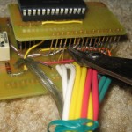
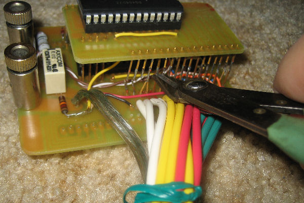
- Removing daughterboard 🙁
-
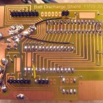
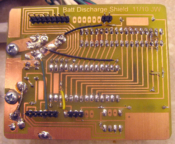
- Seriously hacked PCB
-
- Working!
It hurt, but I clipped off the daughterboard (and removed the cut off pins). There were a LOT of modifications to the board before it was done, but it seems to all work and I think it’s hardware complete.
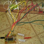
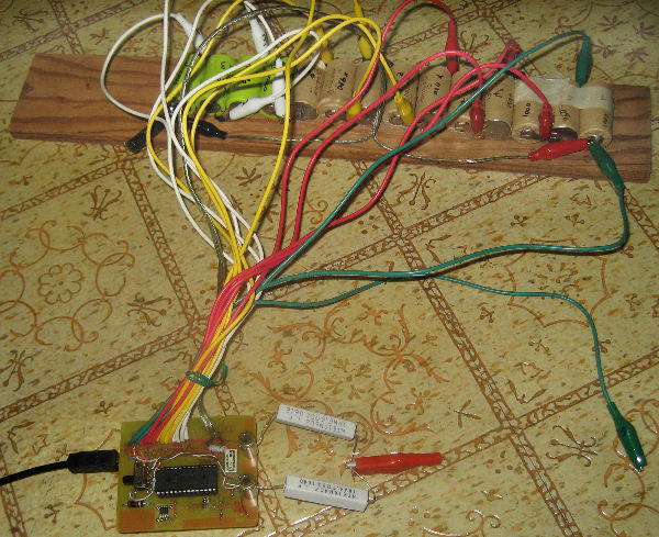
The picture of a battery of salvaged cells under test is pretty much what it was always supposed to look like. You can see the clear zip cord with red and black clips that carry the actual discharge current (and the off-board resistors that dissipate the energy) as well as lonely voltage sense clip #15, not used for the 14 cells under test. I’ve removed the no longer needed slide switch since that picture.
Next steps are a few more bells and whistles for the Arduino code, putting some perl together to process the Arduino’s CSV output, putting the battery tab welder together, and actually rebuilding something! (Oh yeah – and I guess I should do a schematic of how the circuit finally ended up.)