
Thinking there might be need for some more “FDTI cables” – USB-TTL serial adapters with a 6 pin 0.1″ female header to plug into USB-less Arduino clones (like our Diavolinos), and being offended at the pretty standard $15 pricetag of “real” FTDI cables, I found some cheapies – $6 each on Ebay. From China, of course. I bought two, at least to test out.

Cheapie with DTR hack
The obvious drawback was that they didn’t have the universally known FTDI chip. The CP2102 provided about the same functionality, but drivers might be a little less common. Haven’t checked Linux yet, but my Win 7 box found the drivers with no problem.
One of the less obvious drawbacks is that the connector pinout is different from “standard”. Of course it’s male instead of female, but they’re in the wrong order as well. Fortunately, that can be worked around.
Another less obvious drawback is that they didn’t choose to bring DTR out. (They did bring the chip’s Reset line out – why??) The impact of no DTR has to do with the fact that the Arduino IDE/FTDI cable system is cleverly arranged so when the IDE pulses DTR, it bounces the ATMega RST line and resets the processor – invoking the bootloader. This is important when downloading a sketch to the Arduino. If the cable system doesn’t do the reset, you have to be watching and reset the Arduino manually immediately after the compile is done or it won’t start downloading.
I looked at the datasheet, and sure enough the chip does support DTR. Maybe I can just connect to that pin and bring it out on the header. Unfortunately, the pin it comes out on goes nowhere, so I couldn’t pick up the trace on the board. But with some careful soldering, I got a very thin wire soldered to the pin itself. And after tracing the board out a bit, I found I could reuse the dumb Reset pin on the header by just cutting 2 traces and soldering the other end of my wire to a comfortably large pad (the end of the old Reset pullup resistor). You can see the wire in the picture above.

Cheapie with custom cable
Of course the connector gender and pinout are still wrong. But a custom cable fixed that. I tried it out and Arduino downloads work exactly as they should. The labeling is a coat of white-out (correction fluid) on the connector and extra-fine point Sharpie.
A much less obvious very positive feature of the CP2102 is that it has an on-board 3.3V regulator. This really saved me for a while and let me do some testing of the Educube IR boards until a supply of real regulators came in. You can see the long flying lead with 3.3V taped back down to the cable. That wire was soldered on to an IR board to power it for a while. Very helpful.

Second adapter
Now until the displays come in and boards get made, the Educubes only output is via serial to the IDE serial monitor. Figuring we’d need more cables, I took my DTR hack to the second adapter, and this time removed the header and attached a new cable directly. Looks good and works well and is a little more user-friendly.
Overall, I’m pleased with these (as I have been with almost all my cheap Chinese electronics purchases). And the price was certainly right. Unless you count the cost of my labor figuring out the DTR hack, modifying the boards, and making the custom cables. I don’t want to figure that one out.
 Update 1/3/12: I bought some more similar adapters, this time for ~$3 each. These have LEDs for data as well as power. I’m completely comfortable with CP2102-based adapters, as the drivers are very available. I’m disappointed that they don’t bring DTR out, but floored that they felt the need to bring the chip’s reset line out! This version was even stranger on the reset: the external pin goes thru a 2K resistor to the chip’s reset line. No pullup. Huh? Anyway, that made the DTR hack even easier: remove the resistor to get a nice pad to solder to, and no traces to cut. I found some nice blue wire wrap wire whose insulation doesn’t melt as you solder to it.
I had to remove the male header on these, too. This time I used a short piece of #12 solid wire and a bunch of solder to melt all the pins at the same time. (See pic in 2/2/12 update.) Worked out quite well. The cable I used on the first one was too fat and stiff. I went back to ribbon cable for the other two. I did bring the 3.3V output out as a flying lead just in case I ever need it.
One thing I didn’t realize about 2102s until now: That 3.3V regulator is not just for powering external stuff – it’s used internally, so the external logic levels it uses are 3.3V. And the max input voltage looks like it can handle 5V TTL inputs as well. So as I read it, it should talk to either 5V or 3.3V devices. Cool.
I did get slightly burned on this one, though. They reversed the TX and RX labels on the silk screen! It took a little while and chasing traces on the board to troubleshoot that and convince myself they’d screwed up. But after the first one, it’s easy to get the cable right the first time. Looking at the original Ebay post, there’s an extra pinout diagram – but it’s even more wrong than the silk screen. I was sufficiently offended that I even sent a note to the Ebay vendor. I almost wonder if these were the result of some board layout student’s first attempt. At least the price was great!
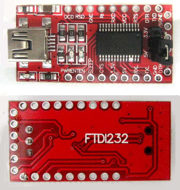
 Update 2/2/12: Here’s some exciting news in the exciting USB-TTL adapter scene: There’s a better CP2102 adapter available! Until now there hasn’t been much reason to choose one adapter over another – and there are lots of these Chinese cheapies to choose from. But this one is a little different: The extra holes along the edges break out many other signal lines – including DTR! No more soldering to a tiny pin on the chip!
I just received this one – for $2.88/free shipping. They didn’t include a picture of the back in the Ebay ad, so finding DTR broken out was a pleasant surprise. My hack to this one was a little different, too: I put a switch on to select sourcing 5V or 3.3V to the connected device.
 The first step was to remove the male header. I used my “chunk of #12 solid and extra solder” technique to heat all the pins at once. A temperature controlled iron provided plenty of heat for the job. The header pulled out intact in a few seconds, and a solder sucker cleared the holes one at a time.
The next decision was how to use the holes from the old header to provide the usual Gnd, Tx, Rx, DTR and power to my ribbon cable. I also needed to pick up both 3.3V and 5V for the switch. Both voltages appeared on the original header, with 5V going thru what I assume is a fuse (marked F1, near the 5V pin). Unsoldering the fuse provides two nice pads – one connected to the old 5V header pin, the other actually providing 5V. I used the former to connect the output of my switch to the cable and the latter as the 5V source for the switch. I took 3.3V from the original header hole – and didn’t connect that one to the ribbon cable.
 The useless original RST header hole will be repurposed for DTR, but first needs to be isolated from the CP2102’s Reset line. A quick inspection of the traces showed a single cut on the back of the board would do that. I considered just running that last line from the ribbon directly to the DTR hole, saving the trace cut and one extra wire on top of the board. That would have worked fine, but using the RST hole seemed slightly more mechanically robust.
Spooked by incorrect silk screen legends on other cheapies, I checked this time by both following the traces and a quick test with a terminal emulator and a logic probe. Sure enough, the legend is backwards on this device. Fine – that’s easy enough to fix when I terminate the other end of the cable. I’m guessing whatever amateurs lay these things out (students?) just don’t know that the convention is to label lines like Tx and Rx from the point of view of the device they’re on rather than what they connect to on some other device.
 I slobbered hot melt on the adapter and plunked the roughed-up side of the switch into it. A little careful soldering of the nice wire wrap wire I found whose insulation doesn’t melt much and it was about done. You can see where the fuse I removed was. I’ll probably cover all the wires with some more hot-melt to keep them from getting caught on things.
If you just wanted a simple USB-TTL adapter with a single supply voltage (pick either one), the only hack you’d need with this one is unsoldering the header and soldering in your cable. That’s about as clean as it gets.
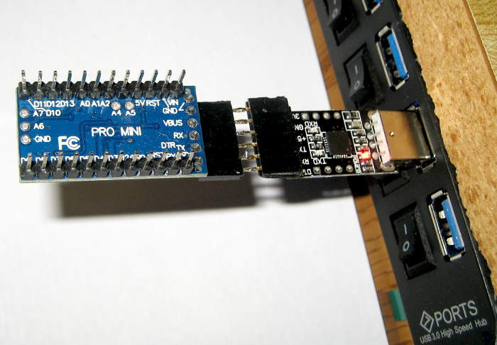
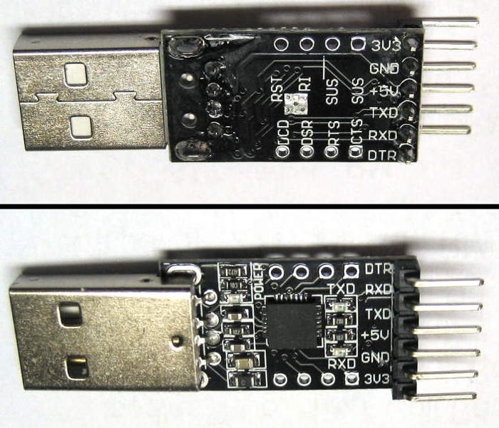 Update 1/2/18: I just got 3 of a new version ($1.50 each), probably motivated to make a dedicated cable/adapter for the Drawbot. Pinout is almost standard, but the end pin – marked 3V3 – should have ground.
A potential hack to somehow use the existing pins would be to cut 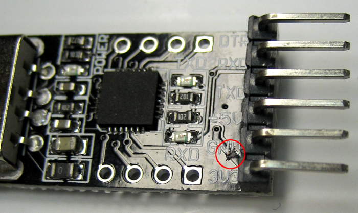 the trace to 3.3V and solder bridge that pin to its neighbor Gnd. Looks like cutting the diagonal trace on the top surface of the board should work, and a quick test seems
 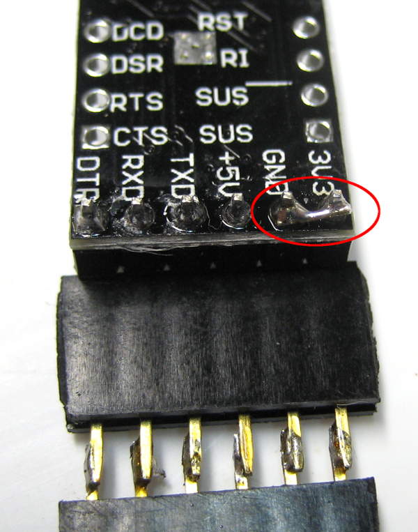 to confirm that. Jumpered end (old 3.3V) and Gnd, made up a F-F header and plugged it into a Pro Mini. It worked – at least in that board.
Update 4-10-20 New red boards
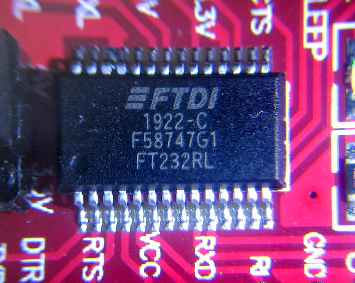 I just got 5 new red counterfeit FTDI boards. The two I checked both had serial # A50285BI, a known common fake number. The chips are clearly illegally marked to look like real FTDI.
 The good news is that they have a 6 pin header that’s actually in the same order as Pro Mini or Diavolinos. It still comes with a male header, but adding solder with a piece of #14 wire the width of the pins allowed me to unsolder the header very easily. It now has a female header, with the DTR end marked green.
The board also has a 5V/3.3V jumper – nice! And yes, it shifts both Vcc provided to the Arduino (or whatever) and the logic levels. All the pins of interest are broken out along the sides, and there are LEDs for TX and RX. So it’s about the nicest board I’ve come across. (Assuming you can accept the counterfeit chip and don’t have the 2.12 FTDI driver that bricks chips.)
The driver for getting a few more of these was to have a module I could add to convert an onboard serial to USB. Don’t remember which one. 🙂
Hi
Great post! And just what I was looking for.
I also have one of the cheapies from ebay, the same as your one from 1/3/12. I also found the TX and RX to be reversed. I followed your guide and soldered on a wire to the DTR and have managed to prove that it resets my Arduino Uno R3 board when I hit “upload”. So far so good.
However, I can’t seem to upload any code as I get the error “avrdude: ser_drain(): read error: Device not configured”. Did you plug your cheapie TTL adapters directly into a board or did you do something special? Did you run your board off the TTL device’s voltage input? Is this 3v or 5v – I got a bit confused in your post about this.
Any other tips?
TIA
Sorry – I’m not sure how you’re trying to use this with an Uno. My understanding is that the Uno has USB in for downloading code (and basic serial I/O), and wouldn’t normally be used with a TTL device like these USB-serial guys.
When I use these with a sort-of-real Arduino, it’s typically with a clone (Evil Mad Science Diavolino with a 328P) that saves a couple of bucks by omitting the USB-serial chip and providing a 6 pin 0.1″ header. Those boards are typically used with an FTDI USB-serial cable, for which the cheapies are an alternative. And yes, I do usually power those boards off the 5V (or 3.3V) from the serial adapter.
As for the supply voltage provided by the serial adapters, it depends. I have a 5V FTDI Basic from SparkFun on which I’ve cut and re-jumpered the very conveniently provided jumper to change it from 5 to 3.3V. That changes both the logic levels and the voltage provided on the supply pin of the 6-pin female. (DTR is right next to ground, and the very next one is the supply pin.) On the CP2102 boards, I believe the logic levels are always 3.3V, although the chip is 5V-tolerant. That means that the logic should work for systems running at either 3.3 or 5V. The ones I’ve seen bring both the 5V from the USB connector and the 3.3V provided by the 2102’s on-chip regulator to separate pins on the 0.1″ header. I typically wire the 5V source to the power pin on the ultimate 6-pin header, and so run the Arduino (or whatever) on 5V. I also bring the 3.3V source out on a spare wire. I’ve done various things to use that 3.3V including kludging a 6-pin female header with the “standard” pinout and 3.3V on the power pin.
I hope that helps!
Yes the Uno has USB + serial I/O with auto reset. Sorry, I didn’t explain…I was testing it on an Uno with a view to using it after testing to program a breadboard-based arduino clone.
Thanks a lot for your guide and tips – I managed to solve my problem in the end.
I finally got it working when someone cleverer than me told me that I needed to connect the DTR line to reset on the chip via a capacitor, and so I used a 100nf capacitor. I understand now that the purpose of this capacitor is to provide a tiny “pulse” to the reset rather than the much longer lasting DTR low signal.
Maybe this tip might help someone else who follows your guide.
BTW I like the way you encased your soldering in epoxy resin- I’ve tried googling how to do this but can’t find anything. Perhaps it isn’t epoxy. Would be interested to know how you do that. I got lucky with the soldering but don’t think it will stand the test of time!
Thanks again, this was a fun little mini project.
Glad you got your stuff running.
The potting on both the board and the connector are just hot melt glue – it makes a little more flexible strain relief. If you need to shape it while it’s still hot, be sure to wet your fingers with cold water first. Works great, though it does leave fingerprints 🙂
G’day Jim,
Nice little hack. Just wondering which traces / tracks you cut ?
Cheers
Is it these positions : http://thrive-image.com/tempimage/board-cut.jpg
Dave,
Yes and no: Here’s what I found in my initial pictures:
http://jimlaurwilliams.org/wordpress/wp-content/uploads/2012/02/Cut1-2076.jpg
http://jimlaurwilliams.org/wordpress/wp-content/uploads/2012/02/Cut2-2073.jpg
The one below the pullup resistor is pretty clear – that was to disconnect that end from +5. My second cut is to disconnect the RST header pin (and the top of the pullup) from pin 9 on the chip, the Reset line. I couldn’t quite see what your second cut was doing.
Does that help?
Jim
Ahhh yes I see now, thanks Jim the pictures are great, I guess I could just remove the pull-up resistor. Cheers
Nice Article Jim
Looking forward, try to avoid the Cheap eBay PL2303 Prolific based adaptors unless its the HX version .
The HX versions have support for Windows 8, the CP2102 chipsets also support Windows 8
Cheers
Rupert
Thanks for this.
I just bought the one in your Update 1/3/12 picture so now know exactly what to do to get it work.
I will look for the Update 2/2/12 in future.
Again, thank you.
I’ve had a few models of the red cp2102 adapters and one batch didn’t work because the solder on the chip shorted a few pins together. I think i had received 5 of these cheap modules at the same time and none worked. I’ve removed some solder and the modules now work, but be careful if your module don’t work the first time, it may not be your fault.
Thanks for the comment, Jon! I haven’t seen that failure yet in the various cheap Chinese junk boards I’ve bought, but now I’ll keep it in mind.
The closest I’ve run across were some nice cheap 1W RGB LEDs, none of which worked. I don’t know why, but I eventually tried the opposite polarity – and they all worked fine. The silk screen on the PCB was just wrong/backwards!
I have secret theory about all this. (Absolutely nothing behind it – pure hot air.) In their grand scheme to take over the world, the Chinese government does even more than subsidize small businesses on Ebay: In their PCB manufacturing schools, the first student exercise is to pick a popular IC, take the reference circuit from the manufacturer’s datasheet and go though the entire cycle with it, from board design through manufacture. Then in a clever win-win step, they take the output – often flawed with freshman errors – and provide it as fodder to fuel the small Ebay businesses. That would explain a lot…
Hi
I have bought a usb-ttl adapter (cp2102 based) but unfortunately its logic level is 5V and I need 3.3V logic level.
On the board there is a hole named 3.3V, Can I use this hole to get 3.3V logic? How?
Many thanks
Hi Jamshid,
I’m not sure how a CP2102 based device could have 3.3V output and 5V logic levels. Is there actually 3.3V on that hole? From the block diagram below, it looks like the 3.3V regulator output is internally connected to Vdd of the UART, so I’d expect the output logic levels to always be 3.3V.
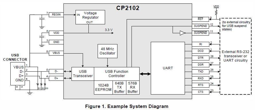
In the datasheet the output levels are referenced to Vdd. I suppose if you didn’t provide 5V in to REGIN/pin 7 and did connect 5V to Vdd/pin 6 you might be able to get 5V logic levels – but it’s pretty scary to run power into the output of a regulator. And the datasheet shows Abs Max voltage on Vdd as 4.2V. Are you sure it’s 5V logic levels?
If you just need 3.3V to power the target stuff, the datasheet says the regulator is good for ~100mA. Since the CP2102 draws 20-25mA, you should be safe drawing 60 or 70 mA from the regulator.
Thanks a lot Jim
I asked the seller and he said the logic level is 5V. anyway I have purchased a logic level converter and finally I may be able to program my broken router.
I bet if you tie vdd to vbus(remove regin) you will get 3v3 io
same as ftdi vccio control, typically you should not use vcc to power external stuff
oh nm, looks like thats usb data line, and there is no similar facility for vio this chip
The cp2103 has vio control, my bad