
There was a nice little wall wart USB charger in the electronics lab at the space for general phone charging, running Arduinos, etc. But when I tried to charge my new phone (Moto G) with it, it wouldn’t charge. Huh?
 Looking at the label, it claimed it was good for an amp – nice. And it said “5.5V”. It was pretty light – no significant transformer – so I figured it was just another cheap 400V-cap-as-series-voltage-dropper supply. OK, maybe 5.5V open circuit, then it would drop as it was loaded down. Put a meter on it – sure enough, 5.5V open. Loaded it to half or 3/4 of an amp – and it was still very close to 5.5V. WTH!? Was it really switcher? (And why 5.5V?) Looking at the output under load with a scope, there was a tell tale ~50KHz ripple. Sure it enough, it was a switcher, and nicely regulated, too!
Lights began to come on: Some sensitive devices will protect themselves from cheap chargers by refusing to charge if the voltage is too high (or too low). And 5.5V really is out of spec for USB power. OK, that’s probably why my phone didn’t charge. (Wrong.)
But this is such a nice little supply. Surely there is some way to use it! I considered a healthy Schottky diode in series, but that was kind of crude. Can I just hack it to lower the set voltage?
 When I cracked open the sealed case, sure enough, there were in fact two small inductors. An 8-pin DIP turned out to be a VIPer12A switcher controller with built in MOSFET. Near it was a 4 pin opto isolator to provide feedback while keeping the output isolated from the line. Nice. As I looked around, I found a 1N4735 1W 6.2V zener. That’s probably what I’ll have to replace. Humpf.
The PCB was just single sided, and I started to look at the circuit. That zener was DIRECTLY across the USB power pins. Must be some kind of overvoltage protection – but clearly not what was regulating the output voltage. I needed to dig deeper.

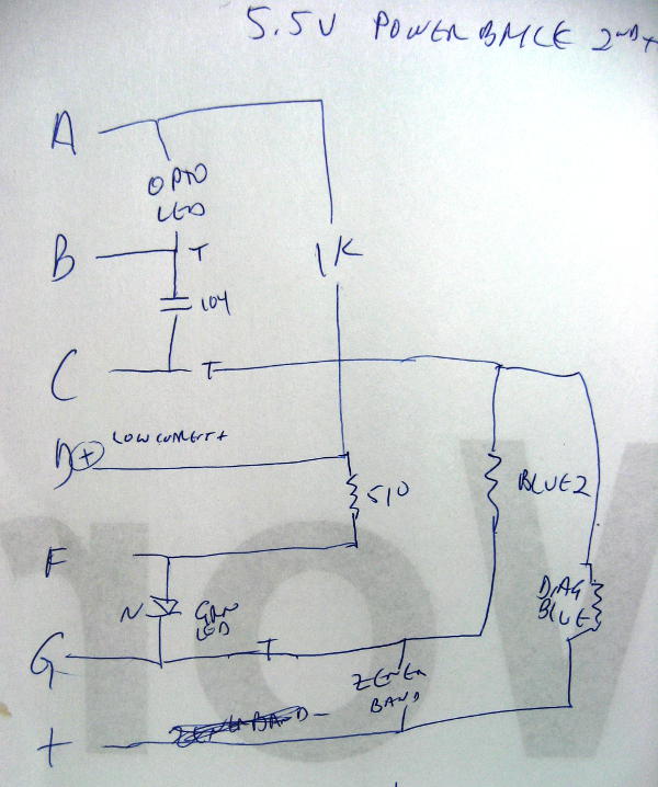 To reverse engineer the bit of the circuit between the USB connector and the feedback opto isolator, after a couple of false starts I tried an approach I hadn’t used before. I took a picture of the foil side of the board, labelled the traces, and then went about making an accurate wire list – which component was connected to which trace – with no effort to figure out what was going on. Then I redrew the components into a rough schematic to see what was what. That simplistic, mechanical task worked well for my foggy brain in the wee hours when I was working on this. Maybe if I were more awake I wouldn’t have needed it.
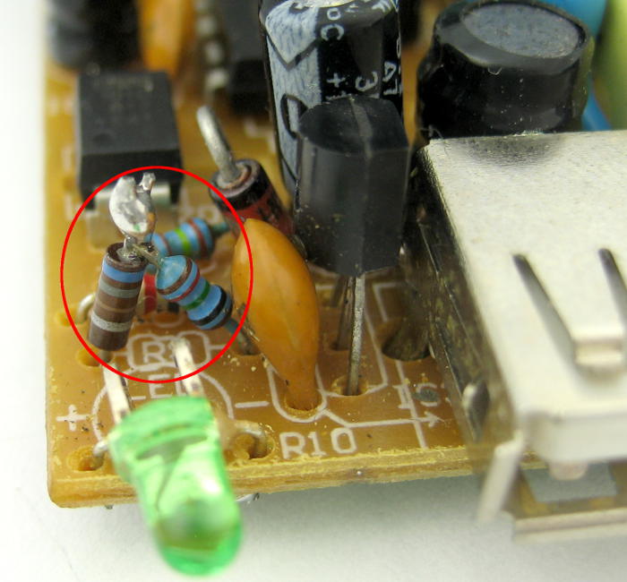
 Anyway, this is what I came up with. I couldn’t read the part number on the TO-92 transistor, so just marked its leads ‘T’ on the wire list. I guessed about it for the schematic, but what I drew seems pretty likely, and makes sense. Two blue metal film resistors with so many bands I couldn’t read them formed a voltage divider across the output. That drove the feedback opto (via a transistor). Great – tweaking a thru-hole resistor is easier than finding a specific non-standard zener.
 After a bunch of cut and try, I ended up with an extra 680 Ω in series with the lower (~10K) resistor. That dropped the output voltage from 5.49 to 5.24. That should keep anybody happy.
I epoxied the case back together, verified that it would in fact charge my phone, and tossed it in the box to bring back to the space. Done!
Of course why they built this nice supply with a standard USB A connector but out-of-spec 5.5V output remains a mystery.
Update a hour later: Damn. I almost never write that I’ve done something until I’ve actually physically done it. But I did it this time – and it bit me. I did remeasure the output voltage (5.24V) after I closed up the case (while the epoxy was still wet). But I finished writing the post before I tested it on my phone. Sure enough, my phone does NOT in fact recognize the charger. Damn.
 Update, a few hours later: Wow. Cut it open again and played with resistors some more. With a 1K resistor, output was 5.18V. Now that HAS to be OK. Tried it with the phone. Nada.
Using my USB breakout cables, tried the phone with my good HP power supply – at 5.0V. Didn’t recognize it. Swapped in another cable. Same. Tried it with another known good charger. Worked. Whoa. Read up on USB charger wiring specs. In the simplest setup, chargers are supposed to connect the D+/D- wires with <= 200Ω. Shorted the data wires. Phone now sees both the power supply and the rehacked (5.18V) charger. Since the case was open, it was a one minute task to jumper the data pins inside the charger, and then both my phone and an iPhone 5C recognized it. Wow.
I knew some phones – iPhones for sure – were fussy about the data lines and chargers, but I never thought MY Android phone would do anything like that. But it does. It probably would have worked at 5.24V – heck, maybe even at 5.5! I epoxied the case back together again. After it set, I re-verified that my phone worked. Really this time.
So now I have what I really need – and thought I had at the beginning: A nice general purpose charger/supply that will charge my phone (and most others) in the lab and provide 5(.18)V when needed. I learn more stuff every day.
Update 6/30/15: It looks like that TO-92 device was probably a TL431 shunt regulator. See updated schematic in the comments. Thanks, er!
TO-92 component, you could not identify, is programmable shunt TL431 or some variation of it.
Wow – How did you know that?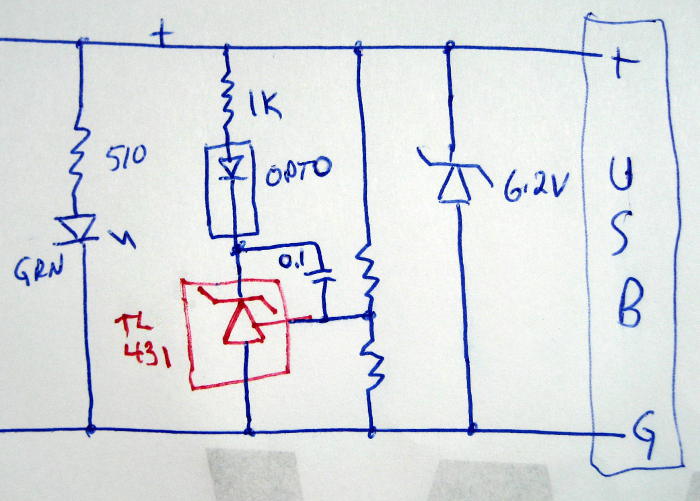
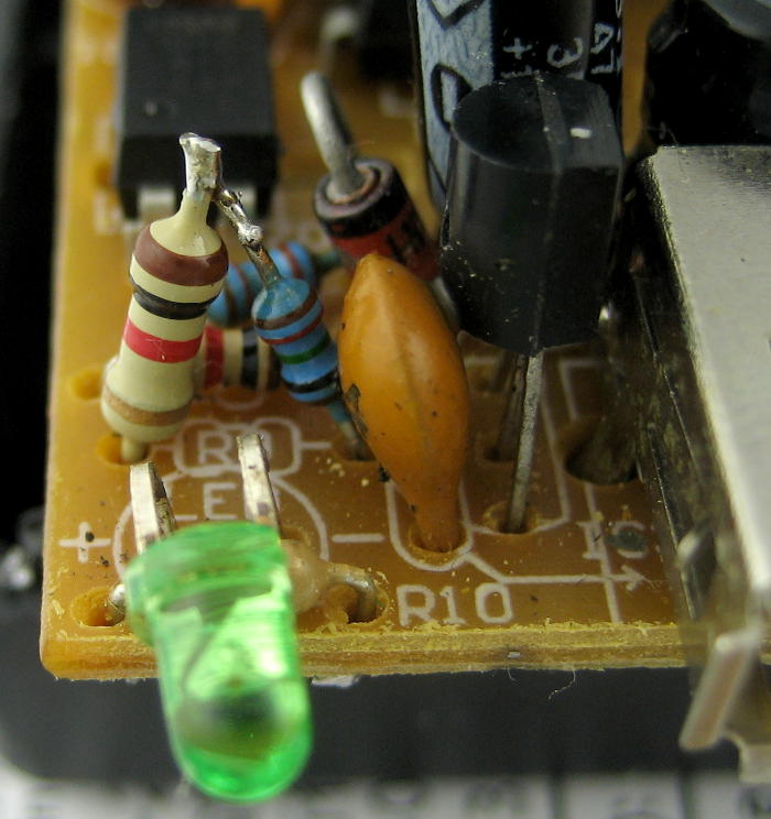
I’d never heard of the TL43x parts. When I bent the TO-92 package over to try to read the part number, I didn’t see anything recognizable, but I have a vague recollection it started with “TL43”. From the orientation of the part and the foil in the pics, and the pinout in the datasheet, the schematic would look like this:
That certainly makes sense.
And even more interesting – if you knew about the TL431 – do you know why they set it up for 5.5V?
just in case that “phone” has name beginning with i… apple decided to be clever with usb standard and now thats the situation: https://www.google.com/search?q=iphone+usb+charging+data+pins
Both my new phone and the old one (which worked on that charger before the hack!) are Android. I expected fussiness about chargers from Apple, but not others. The old HTC Incredible was not fussy; the new Moto G is. Going for simplest first, I was happy when the shorted D+/- pins worked for my phone, and even happier when it worked on my wife’s iPhone. Done!
When I was researching why the power booster pack I bought clicks off every 30 seconds, I downloaded the USB power spec http://www.usb.org/developers/powerdelivery/ USB devices are supposed to know what kind of charger (ampacity) they are connected to, they have some rules about resistance connected to the two USB data leads. It’s complicated. But you might try a short across the data leads to see if the phone behaves better.