
 Yeah, I use unpolarized connectors. Good old 0.1″ headers are cheap, small, plentiful, and I’m pretty comfortable using them. For the power/I2C bus in the dollhouse, they were an obvious choice. But because they’re unpolarized (OK, unless you make them considerably bigger by adding a dummy pin and a plug) I’ve been extremely careful to mark every connector I make with whiteout: White sides go together. I’ve even usually marked the +5V pin as an extra caution (though white-to-white is sufficient.) But Murphy still managed to bite me. Repeatedly.
Troubleshooting time
Something screwy is happening on the I2C bus in the Workshop 88 dollhouse. It sorta works, but especially the light sensors trigger erratically. It needs to be a lot more solid before we can claim it “just works”. Time for some troubleshooting. Two obvious places to look are for electrically invalid signals on the bus and logically invalid messages between the nodes.
To make sure the electrical signals are good first, I wanted to look at them with a scope, but connecting grounds between the scope and the PC USB connection might introduce some noise. So with the scope’s ground not connected, I looked at the DH ground with the scope probe to see. There was what looked like a significant data signal. Whatever’s going on, connecting those grounds isn’t a good idea. (Bite #1.)
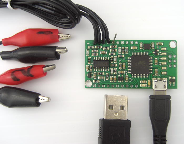 OK – I’ve got this cute little ($20!) dual trace Xprotolab USB scope. If I use that with a laptop running on battery, the grounds are completely isolated. Surely that will give me good results. The laptop’s battery isn’t great, but it should last long enough to make some observations.
Since I’d be connecting to the DH I2C bus repeatedly, I made up a nice little adapter with rings for scope probes or clip leads on a bit of perfboard and a “standard” 4 pin header to plug into the bus. I was very careful to check and 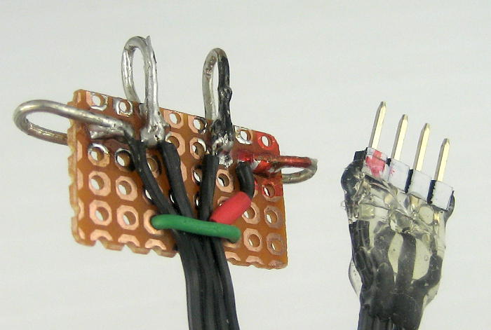 double check the pinout to mark the correct side white, and did a further step of independently figuring which the +5V pin was and then comparing that to a known working connector. Looks good. Fired up the DH so there would be continuous clocks and data, connected Xprotolab ground and CH1/CH2 to SDA/SCL and looked at the scope display on the laptop.
WTH? (Bite #2.) The signal on both channels is almost exactly the same – a pretty clean I2C data line. (The clock line would look different, with regular clocks.) But that’s impossible! I reconnected just one scope channel first to SDA, then SCL. Both were the same. I did various combinations and always got crazy results. Sometimes the signals would even be upside down (going negative from ground). I’d had an arcane problem with that little scope before (trying to show Lissajous patterns in X-Y mode for the Glen Ellyn Library STEAM event). Was it being weird yet again? My head hurt and I gave up.
A little yak shaving…
I did take a little break to integrate the nice immediate I2C command sketch i2crepl from the I2C package I was using into the DH master code. That gave me a tool to exercise individual input and output nodes. Very helpful for a confused DH with sensors triggering randomly. But doesn’t help with looking at electrical signals on the bus.
Then there was another side excursion looking at buying a better scope. My target had been a decent USB scope, but Dave at EEVblog made me consider a venerable Rigol DS1052E. Rats – it doesn’t have a battery option, so no isolated ground. Read a couple of threads on proposed hacks to run it on battery, including designing a new power supply from scratch. Give it up, Jim. Even if you decide to get a new scope, you won’t have it in time to work on the dumb DH. (Interesting, but the wasted time was bite #3.)
I’ve also got a (cheap, little) USBeeSX logic analyzer. I planned to hook that up to capture the actual I2C traffic (again using a laptop on battery) once I was convinced the signals were clean. But I needed to see clean signals on a scope first.
Back to work
Putting the Xprotolab scope (and Rigol reviews) aside, I tried with a trusted bench scope again. The DH also has a coax barrel connector to supply 5V power for “normal operation” mode. I had a little 5V wall wart, and figured powering the DH from that would give me an isolated ground. (Bad assumption, I think. The unit is too light to have a transformer, so it’s probably just a big 250V cap dropping line voltage down followed by a regulator. That wishful thinking was sloppy of me.)
I tried about everything I could think of, including finally boldly connecting the grounds (after measuring voltages first). When I did that the DH went into looping mode, playing sounds that didn’t make sense. Again, some times I’d see impossible signals – logically inverted, and going below ground. Oh – and if I connected directly to the 4 pin connector from the Master Arduino, the behavior was different (and less baffling). It’s biting me again!
 Feeling a little uneasy about the wall wart (and getting desperate), I looked around for another isolated 5V supply. Hey – I think I picked up some cheap Chinese DC-DC 5V USB out converters. <digs around a little> OK sucker – just TRY to tell me that ground’s not completely isolated!
But the bizarre behavior continued. Including inverted and negative-going signals.
Aha
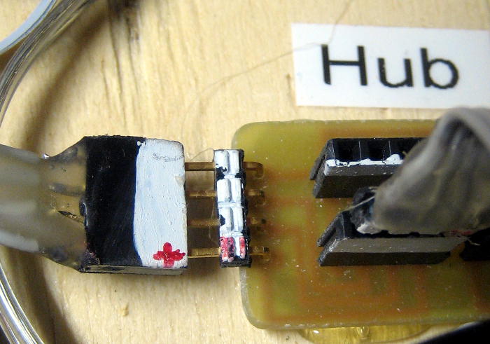
Then I happened to look at the “hub” I’d been plugging my adapter into. Hey wait: looking at the side of the hub, both the female connector I’d been using and the one next to it showed white sides. But the way the hub PCB was laid out, those should have been one white and one not. And then it started to fall into place.
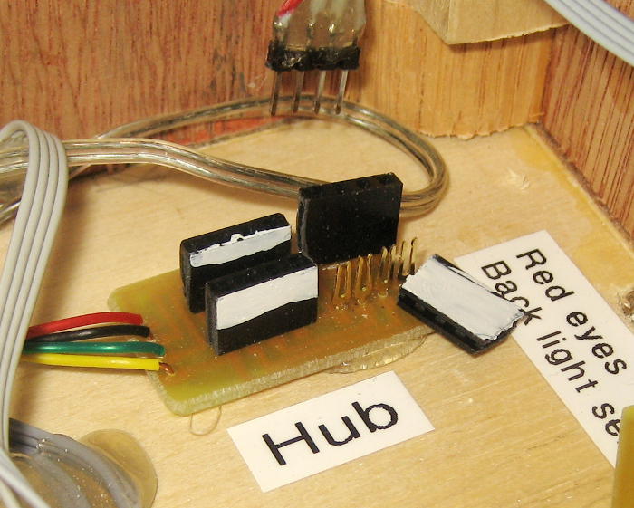 During its travels, the shell of one of the 4 female connectors on that hub had come off, leaving the pins still soldered to the PCB. I found or made another female shell, and forced it on. I’d painted one side of that shell white, but apparently was asleep when I put it on, and put it on backwards. And that was the connector I’d been plugging in to! So all the testing I’d been doing plugged into that hub (with white sides together) had been with the wiring reversed! (When I plugged straight into the Arduino, the hub was not involved, and it behaved much better.)
Damn. With the pinout (+5, Gnd, SDA, SCL) reversed, the “ground” I’d been using was in fact SDA. So with the Xprotolab scope, the pins I thought were SDA/SCL were in fact Gnd/+5V. Both of those showed the same signal (DC shifted, but that’s hard to tell on the Xprotolab) compared to the real SDA as reference. And it explained why some signals seemed inverted, or going negative with respect to the assumed ground (SDA). I guess I’m just lucky I didn’t blow anything out (especially with that probably non-isolated wall wart supply!).
Ah, sanity
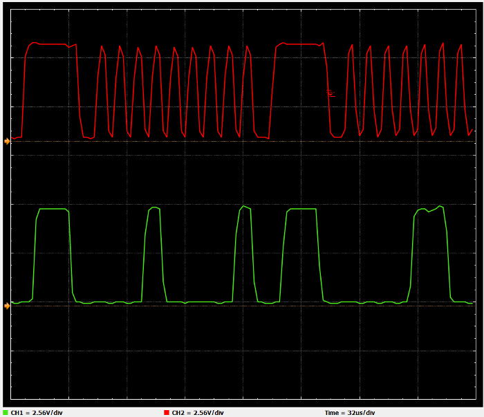 With the DC-DC inverter as supply, I reconnected the Xprotolab scope (with the adapter plugged in the right way this time!) and its display on the main PC. It looked terrible. Then I remembered I was going through a USB hub, and plugged the Xprotolab USB cable into its own USB port on the computer. Much better – it’s completely clear which is clock and which is data. And I looked at how it was hooked up and that agreed. 🙂
It still wasn’t great, and it was at the ragged edge of what that little scope could handle. The screen shot above was at 32 μsec/div. It looked a little better at 16μsec/div, but wouldn’t run at all at 8μsec/div (the fastest setting). At a max of 2Msamp/sec (1M per channel), that’s only ~100KHz – which is the nominal I2C clock rate! It’s not quite enough to see how clean the 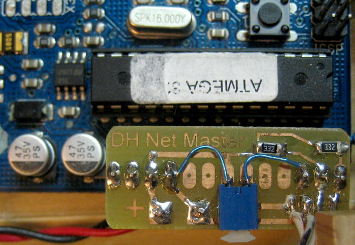 waveforms are, but it does look a little rounded, especially the top corner of the rising edge. The pullups on the I2C bus connector on the Arduino are 3300Ω. Lowering them would presumably sharpen those corners. (Hmm – looks like I put a switch in from A3-Gnd for future use. I’d forgotten that!)
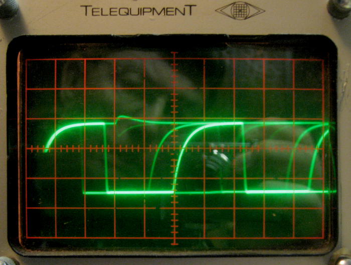 OK – let’s get a little better bandwidth look at this. On the old clunker – but trusted – 5MHz Telequipment scope next to the computer, we see useful information. With most of the DH nodes connected, the clock signal looks pretty good. This says pretty definitively that lowering those pullups would be a good idea, but at least the bottom corners are all nice and sharp. The data line, though much harder to sync on, looked similar. There were some spikes on the high level – nearly a volt – but since that’s not where the logic thresholds are, it’s probably not a problem. Probably.
The next steps will be looking at what’s happening at the messaging and software levels, but that’s for another post. This one – about how much trouble came from one moment of inattention reassembling a connector so a mark was on the wrong side – is resolved.
Update 5/12/14: It’s not part of the I2C bus electrical questions, but just for a little continuity: I resolved the very flaky behavior of the DH. Long story, but after reverse engineering the I2C lib I was using, I found additional read functions that returned status as well as data. By checking the status of each read and ignoring the data on bad reads, it suddenly got much better. I guess checking return values is right up there with not being asleep when you put connectors together.