
 Workshop 88 was given a box (maybe 100?) of as-is laser levels. I tore one apart for the goodies inside (as I expect several others will do). Here’s what I learned.
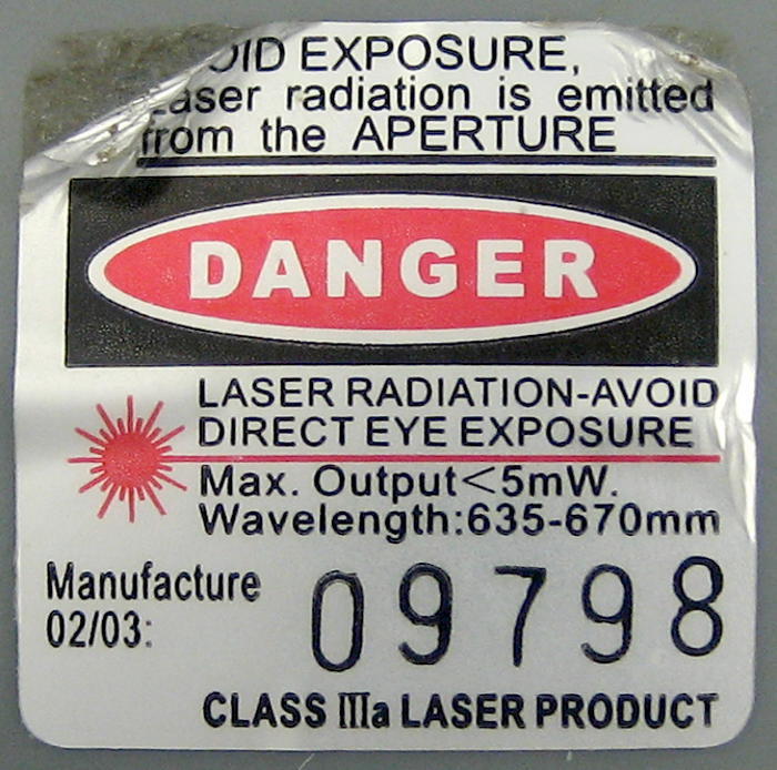
The levels were pretty high quality Keson LL150 commercial units, manufactured ~2003. They ran off 3 AA cells, and 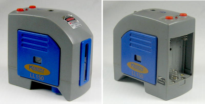 provided spot beams up, down, left and right, and a vertical line out the front. In addition to normal stuff like a lockdown for transport, switches and a 1/4-20 mount on the bottom, they contained 5 lasers and a really nice weighted, gimballed suspension to keep the lasers pointing true. There’s also a clever mechanism that disables the lasers if the case is not level enough to allow the laser carriage to hang freely. While they’d been discarded as old or dead or out of calibration, if they still work, they’re still probably very usable for their original purposes. Of course they don’t all seem to work.
Disassembly
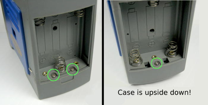 Disassembly begins by removing a small Phillips screw in the top of the battery compartment. This allows the cover to be pulled straight off.
 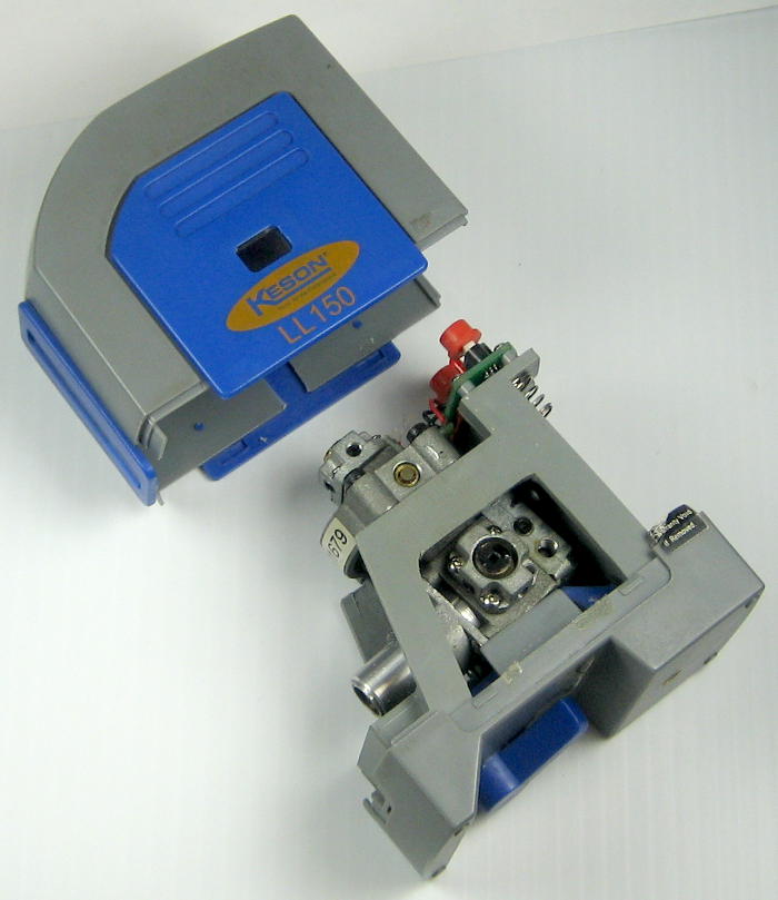 Removing the bottom two will let you scavenge the battery holder later on.
Looking down on it with the cover off, we see the small PCB with the push-on/push-off switches, one for the left/right beams, the other for up/down/front line lasers. It also has a 3.0V 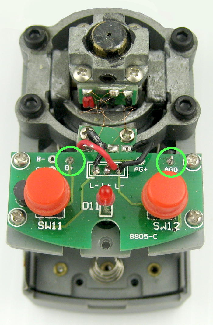 regulator that protects the lasers, as well as mounting for the 3 very fine (read: flexible!) wires that power the lasers while allowing them to move very freely. To power the unit bypassing the power switch on the bottom and the sometimes annoying hang-free sensor, put positive on the place marked B+ and negative on the place marked AGO. That power will still go thru the red buttons and the voltage regulator.
If you’re just inside to look around or troubleshoot with hopes of using it as a level, stop here, and be careful with those wires!
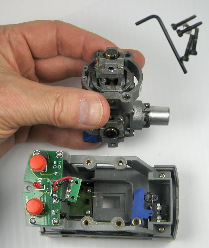 The next step is removing the four black 3/32″ allen cap screws holding the gimbal assembly down. This allows the gimbal/laser carriage to be removed. Yeah, you’ll have to rip off those really nice fine wires. You’re probably going to do a lot more damage to precision stuff than that before you’re through, so come to terms with it.
 At this point, you’ll probably just play with the gimbals for a while because they’re so nice and smooth. But they’re in the way, so you’re probably going to have to tear them off. A couple of people have tried doing so gracefully – like by carefully driving the shafts out of the bearings, but we’ve failed. I ended up doing a combination of breaking and sawing them off. It hurt, but I couldn’t really envision needing gimbals with such limited motion.
Other stuff in the case
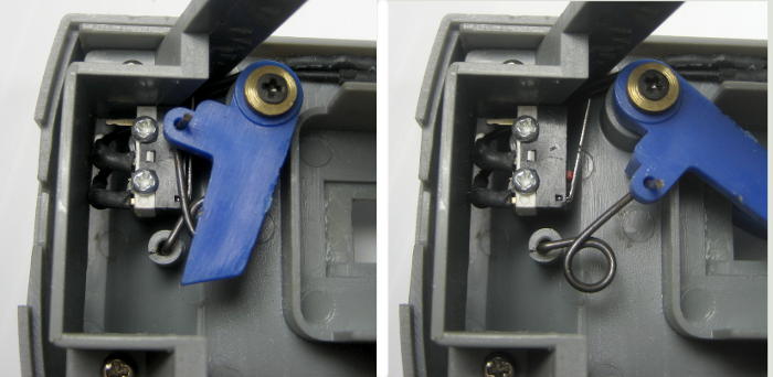 In the bottom of the case frame is the big, hulking blue plastic “on/off switch”. While it operates a small microswitch that is the main power switch, that large lever and its over-center spring does something even more critical: It wedges the carriage against a rubber block in the back so it can’t swing around and get banged up when you throw the unit in your tool box.
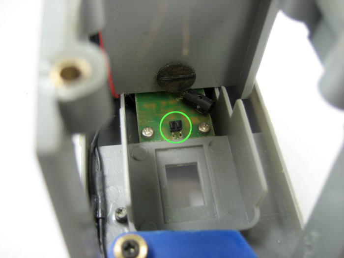
 Also in the bottom of the case – at the opposite end from the switch, and now visible with the laser carriage removed – is the little optical sensor that disables the lasers unless they’re hanging near the center of their travel. The double lumps look like a typical reflectance sensor. Just above it, on the bottom of the carriage, is a small mirror (maybe a bit of aluminized mylar?) that must be right above the sensor for it to be satisfied and allow power to the lasers.
 Lasers!
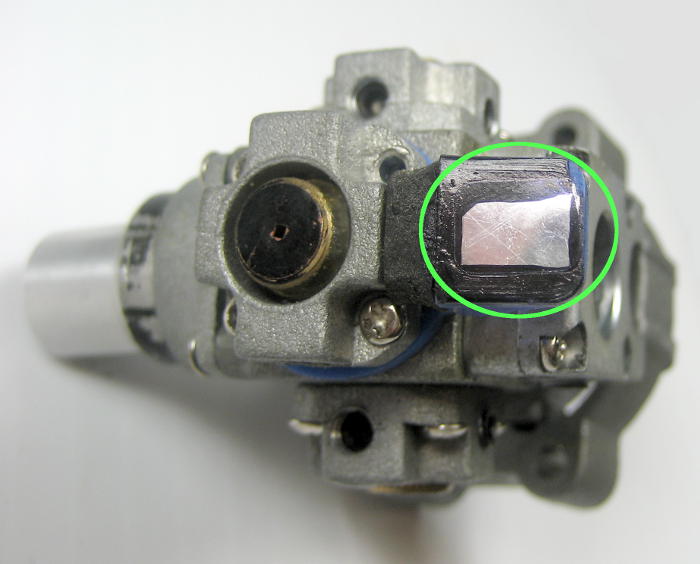
At this point, you’ll probably just start taking the lasers out. You can easily  identify the front laser with its cylindrical glass rod lens for making that nice vertical line. Each laser is in a little cast holder that’s attached with up to 4 small Phillips screws. With those removed, the casting comes out fairly easily. There are wires attached to the back, so be careful not to rip them out
 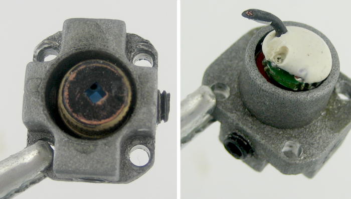 as happened to one of the wires on the one on the right. There’s a bunch of wire and Y-connects crammed into the cavity in the middle of the carriage. There’s probably one laser that’s best to start with so you can get it out with leads intact and maybe do some surgical cutting of the newly exposed wires. I didn’t pick the right one, and don’t know which would have been better.
The actual laser diodes seem to have been put in position and aimed with a couple of set screws through those castings. But then they were epoxied in place, so removing the set screws won’t get you very far. Paul set up a screw press to press them out, but he had a tough time doing it. Given his experience, I just left the lasers in the castings. They provide nice mounting holes, and it’s much easier just to leave them 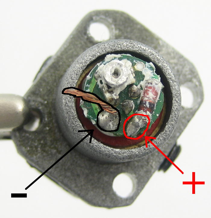 on.
on.
The little PCB on the back of the laser is potted in soft silicone rubber, like RTV. Here’s one with that mostly peeled off and with the terminals marked, in case you have to solder some new leads on. (The negative lead still has some stranded wire attached.)
Power
While Paul and I were playing with some of the diodes on the bench at the space, we ran them up to maybe 5 volts, and watched them draw over 100 mA, and I don’t think we burned any out. But as I was looking at the little PCB in the case (not on the back of the laser), I saw what looked like it might be a voltage regulator. I powered it up and checked – and sure enough there was 3.0V on the laser power leads, even as I cranked the bench supply up and down. That makes a lot of sense for a battery powered device.
Here are some observations of current draw on a complete, functioning unit:
Batt term V  Current, mA, all 5 lasers on
5.0          128
4.0          120
3.5          116
3.2          110
3.0          105
2.5          72
Here's current draw with 4.5V at battery terminals, power on:
No lasers  Side only  Top, bot, line  All
37 mA      67 mA      95 mA           124 mA
The current measurements in the top table are pretty consistent with a low dropout regulator at 3.0V. I’d take all that to indicate that it would run happily on a LiPo . I’m surprised at that 37 mA with no lasers on.
Paul reported seeing a battery life of 20 hours in the manual. With alkaline capacity of say 2000 mA-hr, that’s 100 mA – just about what I saw.
So it looks like we can drive the diodes safely at 3.0 V, and each draws 15-20 mA.
Da loot
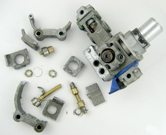
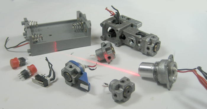 That’s about it. Here are all the bits I managed/bothered to pull out. I couldn’t get the top laser out, so it’s still in the carriage. It took a couple of judicious cuts to get a usable battery holder. All 5 of the lasers in this one work, although it had been marked “B” for bad.
(Well, that’s almost all the bits. I did retrieve the PCB from the garbage, jumper across the removed switches, solder some wires on, and will use that as the regulator to safely power one of the diodes as a rafter-mounted, downward shining “where to stop” parking indicator in the garage. I’ve wanted one of those for years!)
Garage indicator is a great idea, I’ve thought about that but never implemented. A rubber duck on a string does the job for me. Did you hook it to the garage door opener so it doesn’t have to run all the time?
I haven’t installed it yet, but yes, it’s hooked to the garage door opener light. A couple months ago I wired an outlet pigtail (cutoff from a heavy duty extension cord) across one of the light sockets for just this purpose. (And I even used matching push-on connectors so it could be removed and everything returned to the previous state!) So that’s on with the same timer as the light – which should be about right.
I saw the orange outlet emerging from the top of the opener a few weeks ago, and vaguely remembered having made it, but couldn’t remember why. So that’s an extra ‘Thanks!” to Mark for donating the lasers that reminded me what that thing was!
dear all
we are interested with repair and calibration procedures
so we need training on line or you can send us info. by mail
thanks
Hi Raymond,
We’re just a makerspace that got a box of old castoffs and disassembled some for parts. We have no association with the manufacturers, and no documentation, so can’t provide any training about these.
Good luck!
Jim
Hi Jim, I found your space by scouring the internet to find procedures for calibrating self-leveling laser levels. I didn’t find anything, so instead I’ve decided to make a “How-to” YouTube video that others may find useful. I don’t have a an old laser level to tear apart and don’t want to tear apart any of my good ones. However, I need some pictures of the internal parts to accompany the animated videos I made on how to calibrate them. Could I use some of the pics from your website? Thanks!
Hi Paul,
Sure, as I replied from W88, you’re welcome to use whatever pics you need.
I’m pretty sure there are still some levels at the space. If it would help – to disassemble or practice on – I can probably scrounge one or two up and send them your way. Let me know.
Cheers!
Jim
Thanks so much Jim! You’ve been a tremendous help. It would be really great if you could spare a broken one to send me so I can disassemble it for instructional purposes. I’ll email you my address.