I’ve wanted to be able to monitor household water flow for a long time. A primary driver is to be able to spot unexpected use while we’re away, probably involving lots of water going where it shouldn’t – like from an open hose or burst water heater. A secondary use would be as a double check on the landscape watering system.
I had a temperature sensor on the incoming water pipe, and the drop in temperature gave a very crude indication of when water was flowing. I considered taping a mic to the pipe and doing some audio processing on it to sense the noise of water flow in the pipes (but never tried it). The water meter, however, knew the real answers.
There’s some kind of spinning magnet inside the meter. If I could pick up the fluctuations of its field, I’d be all set. I tried all sorts of coils and amplifiers, but while I could marginally detect the fluctuations, the signal was always drowned out by a huge 60 cycle background. I tried my best to null it out, but never could. (Filtering wouldn’t work, as the signal I was looking for could come close to 60 Hz at high flow rates.) While investigating it, I discovered there’s usually around 3 amps (!?) of AC going through my water main. I tried to chase down the cause, but failed. There may well be a problem in some other nearby house that shares a power transformer with us. I gave up on that.
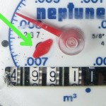 Failing a magnetic pickup, the most promising thing was a little red plastic spinner on the water meter. It makes about 114 half-turns per gallon, so it’s a pretty sensitive indicator. How could I sense it? The white background of the meter was occluded by the spinner twice per revolution. If I looked at the background right under the spinner (tip of green arrow) – perhaps with light of a color heavily absorbed by the spinner – maybe I could detect the spinner’s motion.
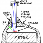 After a couple of simpler tries, I ended up with a telescope focusing an image of that small target spot on a phototransistor. A green LED illuminated the background spot, and the red spinner blocked it enough to detect.
Of course the signal was tiny and ambient light would easily upset 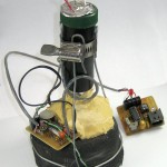 it, so the whole meter face had to be in the dark. And I had to hold the 5″ tall telescope rigidly pointed at the 1 mm square target. A mechanical challenge! First covering the meter with plastic wrap, I built up many layers of cloth mache – strips cut from an old cotton T shirt and gauze bandage soaked in Elmer’s glue. That was kind of translucent, so I painted it black to keep light out.
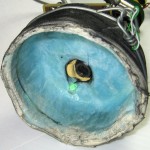 I think while I was laying up the cloth mache I molded in some bit of something cylindrical right above the spinner, and removed it after the housing was dry. That was for the telescope, which might have been the lens and tube from an old 8mm projector, fitted inside a piece of black plastic pipe. A scaffolding of very heavy wire held it in place for initial aim-testing. I think I used “Durham’s Rock Hard Water Putty” to lay up a generous fillet around the tube and the cloth mache base to hold it firmly in place. I also drilled a hole for the green LED so it illuminated the area under the spinner the ‘scope was watching. I have no recollection of why the inside is blue.
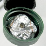 To hold the photodarlington firmly in place on the top of the tube, I found a bottle cap that just fit (from my collection of bottle caps – you never know when you’ll need something like that) and mounted the transistor in it. Of course it took a lot of gain to pull a usable signal out of the transistor, so AC hum was a problem. I ended up shielding the whole transistor and its leads with aluminum foil, with just a little hole for it to peek out at the image of the background under the spinner.
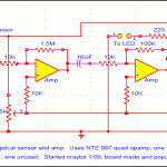 A short shielded cable to a couple of stages of amplification with a good DC offset adjustment, ending in a Schmitt trigger for a clean logic level, and I had something I could run into a PIC node on my home monitor network. The amp is lashed to the main body of the device; in the picture above the PIC node is off to the right. Some careful optical alignment and adjustment of the offset to the first DC coupled opamp stage, and I had an LED flashing for each half turn of the spinner! (Update later: On looking at the schematic, I’d expect a DC path to ground after the photo tran, and with that 22μF cap, the first stage certainly isn’t DC coupled. It obviously works; sorry about the design and/or explanation.)
A little custom PIC assembler for the RS485 node, some perl to add the new node to the main house monitor poll and report cycles, some php to read the new data and put up a graph of it, some fiddling with calibration constants, and I had water usage on my home page. It ran happily for a couple of years.
I pulled it off to look at it or show someone or something, and it stopped working. It was down for another year or two, and I even had to put a comment on the water usage graph on my home page that it was temporarily down.
Just a month or so ago, I got it going again by simply running some water and slowly twisting the whole device on the water meter and watching for the LED to start blinking. While the cloth mache housing was fitted around the black plastic cap over the 3 screws that fed the wire to an outside reading device, that wasn’t quite enough to register it perfectly. This time I carefully put some registration marks on the bodies of my contraption and the water meter so I could put it back on successfully if I ever had to take it off again.
And then just a few days after it was working again I took it back off and began the trek to read the meter first via the radio the meter reader uses, and then directly off the 3-wire interface from the meter to that radio. While I was eventually successful in reading the meter that way, the granularity of information I could get was orders of magnitude coarser 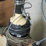 than my old optical approach. I’ve now hooked the original wires back up, put the plastic cover back over the screws, put my big black thing back on and am back in business.
And nice try, but no cigar on the registration marks I recently put on: The “register” part of the meter that contains the dials (and the spinner the telescope looks at) is removable, and in working with it I twisted it in place by many degrees. The mark I put on the meter was on the lower body of the meter, not the register, so the marks are no longer meaningful. Boo. But the “twist it until the LED blinks” trick worked and it’s up again. (Have to be careful when using that technique to twist the telescope housing with respect to the register and not just let the register twist in the meter body.) And I finally got to take that comment off the web page that the water meter is broken!
(I would have sworn I took pictures of this as I was building it, but I’ve searched all the picture archives, backups, old cameras and cards, and even pulled the disk out of the previous main PC that wouldn’t boot any more, but couldn’t find anything but the schematic of the amp. All the (other) pictures here are very recent. Sorry for no pics of laying up the cloth mache housing. It was a very interesting, if messy project.)

Pingback: Interfacing to my Neptune water meter | Jim's Projects
I have a couple of these I bought years a go to inspect fiber optic connectors. I could try your idea with one of them. Though I would have to saw the nose off the microscope to get it to focus.
Wow – looks like it might work. Do you have a spinner on your meter like mine?
I think it does, have go in the crawl space to look. The microscope is 60 power minimum zoom so focus will be a problem. Also would have to get power to the unit. I took it apart yesterday and am installing a white LED instead of the flashlight bulb that’s in it. Wonder if green LED would give more contrast with a red spinner.
Hi Jim,
You probably haven’t thought about this in a while, but I’m starting the task of trying to parse images from my meter. I use a $40 raspberry pi and $7 web cam to capture an image of the meter every minute. I’ve been collecting images now for a week, I have yet to start experimenting with how parsing will work, but I can let you know how it goes.
Jeremy
Sounds cool, Jeremy! Yes, I’m very interested in hearing how your approach works out. What are you using, OpenCV?
If you can get it to work, I’d be happy to follow your lead and replace my “interesting” but ultimately unrobust hardware sensor.
Please keep me posted!
Jim