
I’m getting really close to my goal of having a solid, standardized, manufacturable square dance recording device. I just sent out the Gerber files to have the first run of circuit boards made! The earliest notes I can find about this project were from March 2005, so I’ve been working on it for a long time.
I’d planned to make the PCBs myself, but when I ran across an offer for ten 5 x 5 cm double side boards with plated through holes and silk screen for $9.90 from SeeedStudio, it was too good to refuse. The existing boards were about 5×6, so I had to move a bunch of stuff around on the board to fit the smaller outline. By the time I was done, I wanted some warm fuzzies that I hadn’t messed up, so (working on a copy of the layout!) I made a couple of minor hacks (like adding pads for jumpers for the few traces that were on the bottom side) and made up a single sided board.
I used my now standard ink-jet-printed transparency artwork and pre-sensitized boards, but must have been distracted: I skipped the development step, and put the board directly from the exposure holder into the etch bath! I’ve never done that before. Fortunately, the resist is developed away in the exposed parts, so the whole resist layer was intact for the minute or two it spent in the etchant before I realized what I’d done. I pulled it out, rinsed it off well, developed it, and etched it. It came out about perfect, as always, despite the missteps.
Unfortunately, populating the board didn’t go as well. I used solder paste and soldered by hand. I think there’s spatter from the solder paste if it heats up too fast (which is easy to do with an iron), and I ended up with shorts to traces passing under a couple of resistors and so much trouble with the (0.5mm pitch) 2167 that I had to take it off with a hot air gun and put it back on from scratch. I ended up scrapping that board – which I’ve never had to do before.
But as a result I cleaned up the layout some – moving things so I had only one trace instead of two going under one resistor that had shorts under it, increasing clearances in several places. Oh yeah – and fixed an error that reversed the power supply leads to the Sansa! It was connected that way for a couple of minutes while I tried to figure out why it wouldn’t light up. When I noticed it was also getting hot I pulled the battery until I figured what I’d done. Oops. But in an incredible stroke of good luck – and robust engineering from the Sansa designers – it survived apparently unscathed, and seems to still work fine.
 But I’d made several more changes, and still wanted warm fuzzies on the new layout before I sent the files out to the board house. So I made up one more single sided version of the board, this time being less generous with the solder paste, especially on the 2167, and reflowing it instead of doing it by hand. MUCH better. The one simple bridge on the 2167 came right off with some solder wick. (It’s really small – there’s a 1206 resistor just for scale. The traces immediately off the 2167 pins are 10 mils.)
 I wanted to test the electronics without having to completely assemble everything first, and since I’ll be building a bunch of these, I made up some test bits I could tack solder on for initial testing. I expect I’ll use the audio in, battery/power supply leads and Sansa hook up with each board I as I test it. And yes – it all worked first try this time.
Update 8/26/12: Since I’m going to have to test quite a few of these things, a test jig is a good idea. Tack soldering leads on works, but I’d often have to use solder wick to clean out holes even if I didn’t actually solder wires into them.
 So I made up a little “bed of nails” tester. I was too impatient and cheap to order pogo pins to do it the right way, so I just soldered some pieces of the solid #20 hardish copper wire from telephone (outdoor?) station wire I also use as the connections and mounting pins for the Sansas at a shallow angle as slightly spring loaded contacts. They’re maybe 1/4″ above the board at the free end where they touch the holes in the board under test. I used the original board layout in Eagle to locate the contact points – the centers of the 3 Sansa pin holes and the 2 holes for the audio input cable – left small circles on the tester board in those locations, and laid out small rectangular blocks to solder the wires to that pointed them to those circles. From the almost straight-down perspective of the picture, you can see one of the circles a little below the tip of the upper right hand pin/wire; the lower left hand one’s tip is directly above its circle. I taped an old Sansa battery (I have lots!) to the board so it can power the Sansa and electronics without bothering with a power supply. I put a switch in series with it because it seemed like a good idea. 🙂
The external connections to the recorder board under test are the 3 Sansa pins, the 2 leads for the audio cable, and the 2 leads for the battery. But since the battery leads are also wired directly to the Sansa, there was no need for additional pins to contact them.
The 3 Sansa leads are brought out to female pins from RS-232 connectors that fit (poorly) either the 0.025″ pins from one of the early Sansa like the one pictured or the #20 wire pins of a Sansa built to solder to the board. The latter allows testing with the actual Sansa I’m about to use before soldering it in place.
 Since my usual audio test source is an old Iriver (that used to be a mainstay recorder!), I needed a 3.5mm male plug to connect to it. Following my preference for pig tail leads, that’s what comes off the tester board. But because I needed to mix the two stereo output channels of the Iriver, I put a couple of 22Ω resistors on the tester board to avoid connecting the two outputs directly together. Here’s a pic of a board ready to test. Yeah, I have to bend the “springy” wires back up maybe every other time I use it, but it’s quick and it works.
Getting ready to send out for boards
Trying to get all the information needed by a board house – silk screens, solder masks, board outlines, in addition to the basic traces and pads and vias – in the right format is a lot more complicated than making up B/W artwork for my simple single sided boards. Fortunately, Seeed’s Fusion cheap PCB service has been around for a while, and in addition to their page of instructions on how to submit your board files, there’s an FAQ, an independently contributed set of more detailed instructions, and a forum where many of the beginner questions are posted and (mostly) answered.
Seeed provides an Eagle design rule file that knows stuff like minimum trace widths and various clearances, so you can run a Design Rule Check in Eagle to catch some kinds of errors. It also provides a CAM processing file that lets Eagle produce Gerber files in the required RS274x format. And someone highly recommended checking the resulting Gerber files with a Gerber viewer like the open source gerbv, so I have that useful tool as well.
After a LOT of iterations through those tools, checking the forum, tweaking the board design, and slowly becoming more familiar with how it all fit together, I was ready to start the two-step order process. I placed an online order for one instance of the PCB service for 10 5×5 boards with options yada, yada. It came to $14 with shipping (from China). I got an email back immediately with my order number. Then I sent an email with my Gerbers, referencing my order number.
Now I just sit back and wait. Oh, and make up a Bill Of Materials. And make sure I actually have enough parts to build these things up. And finalize the mechanical mounting details, and finish putting the two boards lying around with temporary leads flapping into their permanent cases. And start modifying the pile of Sansas I’ve found on Ebay. Oh yeah, and figure out what to do about the Rockbox firmware bricking V2 Sansa Clips. (Clip Plus and V1 Clips seem to be OK.) So much for sitting back…
The Sansa Clip V2 problem

 There are 3 variants of the Sansa recorders in play. My original line-in hack was to the “Clip Plus”. When I needed some more, I found lots of the model called “Clip” on Ebay, and they seemed to work. In fact the mechanical modification is slightly easier with the Clip. But as we’re modifying the firmware, the more subtle distinction between Clip Version 1 and Version 2 becomes important. The code is different for the two. Fortunately, they’re easy to tell apart just by looking at the back.
After I had all my code tweaks in place, I thought all I’d have to do was build for the correct target hardware. There’s even a configure script that sets the appropriate defines. So I built for a ClipPlus, ClipV1, and ClipV2.
The first time I loaded my custom version on a V2, it bricked the device. I grumbled, and the next one I picked up was a V1, and it worked fine. But when the second V2 I flashed didn’t work right (functioned, but was not recognized over USB), I started looking into it. It looks like (at least some) versions of Rockbox at least some times brick V2s. Not good – I have several V2s in my stash.
Fortunately, there are (rather arcane) instructions on how to unbrick a V2 by opening it up, and booting it from cold while 2 test points are jumpered. This brings the device to a special ‘recovery’ mode, where at least it will boot and it will show up as a storage device via USB. You can then dd an image of the original firmware in from a Unix box, and at least have it running the original firmware. I haven’t tried that yet. I did the boot-while-shorting-2-pads dance and brought a bricked V2 back from the dead. Many thanks to the Rockbox community for making info like this available!
I also don’t know whether the version I’m building my custom on top of is one that doesn’t play well with V2s. Maybe if I just redo all my tweaks on top of a later version of Rockbox it will work. Much more to discover.
V2 update 8/21/12: Rockbox code used to be managed under svn, and I’d gotten to the point that I could grab the latest code base from that system. Between the code I’d modified and made peace with that worked for Clip V1 and ClipPlus and now, they moved to git. Nothing against git (and I think I might even have made a little git repository for something once upon a time), but I’m not familiar with it, so it took a couple of tries downloading various clients until I could actually get current Rockbox code. They also changed (at least the internal) version numbering, so all I can report is that what I grabbed seems to be “b61b14f”. And for reasons I’m sure some of the devs felt were good, some of the code was restructured so some of my changes were no longer in the files they used to be in. But grep is my friend, and I eventually found where to put all my hacks. (Hmm – it’s not clear whether I updated the “mychanges.txt” file that listed the changes and filenames.)
The good news is that after I put my changes in and built for V2, the code loaded into a Sansa V2 and worked. I think I’ve put it in at least two V2 units with no problems. So whatever the ‘brick’ problem was, at least this code version seems to have fixed it. I am however now pretty religious about upgrading any new Sansa to the very latest Sansa firmware before installing Rockbox, and always using the latest Rockbox installer.
Of course it would be nice for all the images I install to be built from the same code base. I tried rebuilding V1 and ClipPlus with the new code (it’s just a build flag), but ran into some kind of problem. I should go back and address that. But worst case I have my old V1/Plus image and the new working V2 image.
Anyway, it’s nice that I don’t have to try to sell off all those V2s and start asking questions to identify V1s before I make Ebay bids.
Bill Of Materials
1 PCB (board house or homebrew)
1 SSM2167 (mini-SO-10)
1 LM3914 (PDIP 18)
10 LEDs (1206 SMT or 2x5LED HP strip from ElecGoldmine)
3 10uF SMT cap, pref 1206
2 1uf SMT cap, 1206
1 1.5K resistor 1206
1 2.2K resistor 1206
1 2.7K resistor 1206
2 4.7K resistor 1206
1 6.8K resistor 1206
1 22K resistor 1206
1 33K resistor 1206
1 68K resistor 1206
1 FDV30 N-chan IGFET SOT-23
1 10K audio taper min pot Digikey P3D4503
1 RCA male cable 18-24″
1 plastic case 2.5″ x 3.5″ like Container Store 10054865
1 850 mA-hr LiPo battery like SparkFun PRT-00341
Servo tape, epoxy, solder paste and other assembly necessities
1 modified Sansa Clip or ClipPlus 1GB or larger
1 small PCB for mounting external leads to Sansa
2 thick 4-40 nuts with captive lock washer
2 4-40 x 3/16+ flat head machine screws
1 USB mini-B 5-pos cable with small connector body
1 copy Jim’s user manual
1 copy Jim’s custom Rockbox software (currently based on 31180)
plus whatever else I’ve missed…
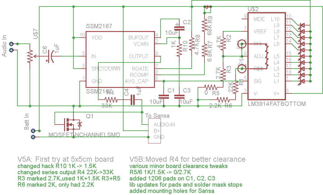 And just for reference, here’s what I think is the final schematic:
Got boards!
 The boards just came today 6/27, about 15 days from when I sent the order in. Not bad. And there were 11 boards instead of 10. Can’t ask for more.
 They look great! Even if I went to the trouble of figuring out how to reliably make double sided boards (and stocked double sided board material, etc) these are way nicer than anything I could make. The silk screen on the back will show through the translucent case, and on the front it labels (if tinily) the level control and even has interlocking squares.
I guess I oughta stop oohing and aahing and build one to see if it actually works 🙂
 Update 8/21/12: The boards seem to work fine. I’ve made up 4 of them so far. The only problem I’ve found is that I failed to stop the solder mask in two spots where I solder the case of the level pot to the board. There was never a problem for my simple single sided no-solder-mask homebrew boards – I could solder anyplace I wanted!

 Here’s the soldered place and the scraped off mask. Not a big deal to fix – just a minute or so with an Xacto knife.
I’ve reflowed all four boards so far, and that has worked well. But I still have to be careful of solder balls that form when  I put too much solder paste on. Balls this size wouldn’t be a problem for most boards, but with that 0.5mm pitch 2167, these balls could cause trouble. I’ve added an inspection step to look for and knock off these little buggers.
 Here’s one of the production models made up. I’ve actually delivered the first one (to Ron Hazslip – yay!); this is number 2. The only bit missing from this one is a shield/cover made from clear clamshell packaging plastic over the battery and visible parts of the PCB. I’ve started to make a template for that, but it doesn’t fit very well yet.

 While the board is laid out to accept either 1206 SMT LEDs or the thru-hole 5-LED blocks from Electronic Goldmine, all 4 so far have the thru-hole ones. They’re mounted funnywise at an angle to make them more visible from the side. Looking down from the top they’re still quite visible, but this way there’s enough light going about parallel to the board that you can see them acceptably through a hole cut in the side of the case. This makes it possible to check that the LEDs are bouncing without having to go up to the caller’s table and look down on the recorder. A nice feature that pretty much works as designed.
Where they went
I started to lose track of how many of these things I’d made up, so here’s a place to store the history.
I started with 3 newish prototypes in my recorder bag.
* Seeed board #1 went to Ron H at Romney weekend 8/12.
* #2 went to Tony Oxendine 8/22/12.
* one of my newish prototypes (single sided test version of Seeed layout) went to Noah Siegmann 8/22/12. I need to make a Seeed board up to replace it.
* #3 will go to Tom Miller probably delivered at Turkey Run Adv weekend
* electronics are done and tested for # 4, 5, and 6 – one Sansa modified so far
Some mechanical details
Mounting the Sansa involves some manual work. The initial modification to the device includes epoxying a small PCB inside that provides a sturdy place to solder the 3 heavy wires coming out of the back of the case that  do double duty holding the bottom of the Sansa to the board in addition to providing electrical connections. There’s a little spacer to hold the lower end the right distance from the PCB. Looks like I haven’t rounded off the corner of this board yet.
The main mechanical mounting is two 4-40 machine screws near the top of the PCB. Nuts are epoxied to the back of  the case (after sanding to provide some “tooth” – I seem to have gone overboard on this one). The alignment of the nuts is assured by putting the screws thru the holes, tightening the nuts on and clamping the whole thing together as the sparse initial epoxy sets. After that it comes back apart and I build up a generous fillet of epoxy around each nut. It turns out 1/4″ screws are too long and 3/16″ are too short, so I have to run a nut on a 1/4″ screw, grind a few threads off the end, and reform the threads as I take the nut back off. Not too hard, but it’s an extra couple of steps for each one I make.
 I cut the plastic shaft of the level adjust pot down so the case closes comfortably. Not using a knob provides a little extra protection for the pot from being bumped and misadjusted. To provide an index line, I saw a small slot with an Xacto saw and fill it with white-out. Some black magic marker on the top helps the contrast.
You can see the hot melt strain relief for the coax input cable in pictures 2 sections above. Cutting the little edge-view window for watching the LEDs while the recorder is on the table is a slow, careful exercise with an Xacto knife. I’ve tried roughing it out with a cutter and a saw blade on a Dremel, but there was no major time/effort savings. Hmm – I wonder if a jewelers saw would help on the rough cut? I’ll try that next time. “Servo tape” sticks the parts in the case well, but allows disassembly if it’s really needed. There’s even marking for where the tape goes in the silk screen on the back.
 The last mechanical detail (after putting the annoying warning sticker on the LiPo) is a thin clear plastic cover to keep stuff out of the PCB, be the glazing for the edge window, and provide a little extra protection for the battery. (Yeah, yeah, it’s a cell, not a battery.) I’ve tweaked the template so it pretty much fits first try when I cut one out. And I even scanned the template to a soft copy so if that little beat up bit of card stock gets lost I can still make the plastic covers.
Wonder if you’ve ever tried ammonum persulphate? Ued to use that all the time to make commercial boards. It was much easier to handle and much more stable. It also doesn’t stain like ferric chloride.
Regards,
Paul
P.S> Nice job with the preamps 🙂
Yeah, ammonium persulphate was my etchant of choice before I started down the cupric chloride path. The problem was how to get rid of the used stuff. I’ve got several bottles of pretty blue used etchant sitting around. I’d heard that you could just dry it out and take the dried copper salts to a haz waste disposal place. But I’ve had something like a square 9″ cake pan of it sitting open in the garage and it’s still mostly liquid after a year or so.
I’m sure I could find something that would precipitate the copper out somehow to do the same thing, but haven’t found it yet.
Thanks, the boards did come out nice. I built one whole recorder up on one of the boards and it works perfectly. The only imperfection in the board is a place I failed to mask off the solder mask. There’s a PC mount pot in one corner (above the “Level” label). Its pins go thru the holes, but for mechanical support I solder the edges of the case to the square of copper that sits under it. The solder mask covers where I need to solder. Wasn’t a problem on my home made (solder-mask-free) boards, so it never occurred to me to put a mask keep-out there! Not a big deal to scrape off enough mask to solder, but felt kinda dumb the first time I went to mount that part.
Guess I oughta post an update about it. Thanks for bringing it up!