
I ran across running Neopixels with just 2 wires here. Looked neat.
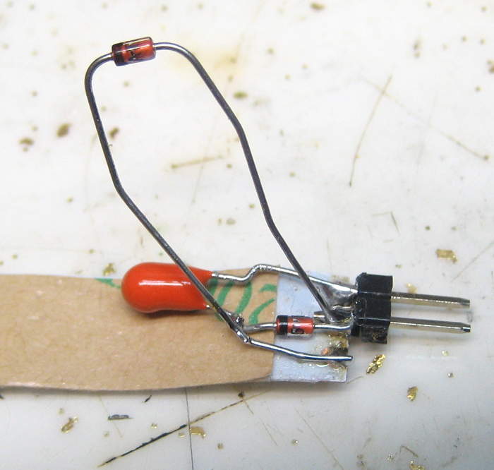
 Unfortunately, despite many much more pressing tasks, that was too shiny to pass up, so I decided to try it. Won’t take too long, right? Following a pic in Tubular’s article, I soldered a 33uF cap and a BAT85 Schottky diode to the input end of a 5 LED WS2812B strip with a 2 pin 0.1″ header as input. Fired up strandtest (with setBrightness(5) to decrease power), setting an adjacent pin as “ground”. Nothing.
OK, we’re way out of spec anyway – maybe the ground isn’t good enough. Tried a real ground. Got maybe a few flashes (of more than 1 LED – so it must have been talking at some level). Moved to pin 13, since that has a real ground next to it on the Arduino header. Same – nothing more than flashes.
Back to original pins (A0/A1) and touched +5 to the power pin on the strip (with diode and cap still in place) – strip worked fine.
Article was originally on Parallax Propeller – do they have crazy high drive capabilities? Checking… It’s a 3.3V part, and 40mA/pin max – same as Arduino. OK, possibly lower output impedance, but not a huge difference.
OK, it’s a really clever idea, so what if I provide data pulses with more oomph behind them? I happened to get some APM5943 (dual) logic level P-channel MOSFETs in the mail today, and so in my shiny-drunk took that as a sign/opportunity to try a full-power pulse train as input to the 2 wire device. (Of course we need P-chan to provide high-side switching.)
Commence yak shaving
Unfortunately, those FETs are in an SO-8 package. They’re not very useful for testing that way, so I really should make up some little breakout PCBs (like I did for the FDS6670 N-channel SO-8s). Looked a little for an Eagle footprint, gave up and decided to make my own.
I’ve never really understood FET symbols, and I wanted this to be right, so I dug in a little. “Source” and “Drain” are inverted on P-channel v N-channel. Who knew? And that means my one small memory crutch that “Source” sourced electrons only works for N-channel devices. Rats.
I think I got that all sorted, and made the Eagle library part. Of course in normal operation, unless you have a reliable rail-rail drive signal, you most always will want a gate pullup for a P-chan MOSFET, so I put some pads for 1206 resistors on the board. Tried to make up a 6-up board of them, but you can’t copy stuff from a board with a schematic in Eagle. Copied the whole board file (to new name) without an attached schematic, and then Eagle 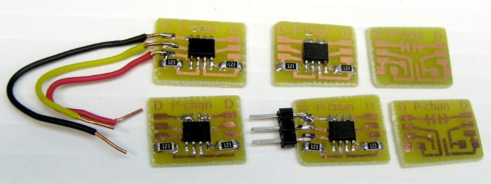 let me copy/paste my 6-up. Etched the board without much trouble.
Can’t find my solder paste. WTH? Fine – populated 4 of the breakouts by hand instead of reflow. Wired some flying leads. Ready to try it out!
Back to shiny testing
Hooked the hacked WS2812B strip and MOSFET up using real +5, real ground, and my data pin. Got very bright flashes, followed by Arduino reset. In a loop. Disconnected, scratched head. Somebody’s drawing too much current.
Crap – the MOSFET inverts the signal! I’d realized I’d need another transistor to pre-invert the signal (being too lazy to invert it in the library), but forgot about it. Fine. Rechecked LED strip (with real 5V) – still works. Good.
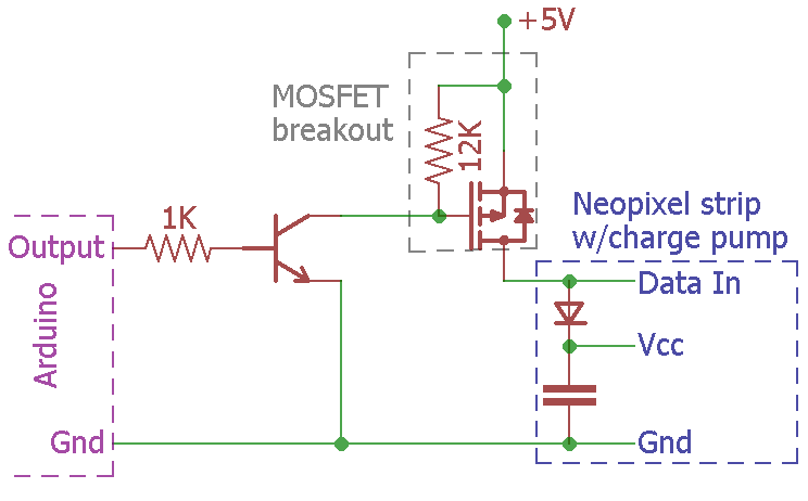
 A little breadboard, a 2N2222 with a 1K base resistor as an inverter and it was ready to try again. Tried. Nothing. Looked at derived power pin with a scope. Noisy (as expected), but only around 1.5V. That probably won’t work. Time to dig deeper. (So much for a quickie project!)
On the bench with the good scope, I could see the bursts of serial data on the Arduino data pin, but not on the Din pin of the LED strip. Huh? OK – data at Arduino pin. At the 2N2222 base, after the 1K – no. Cut the 1K to 220 or something, and saw barely valid data pulses. I can’t drive the 2222 fast enough. We’re doomed. Yeah, I could find a faster transistor, but no.
As long as it was right there, I looked at the MOSFET drain/Neopixel Din. Of course I could see a pulse for each strip.show(), but not the individual data bits. Connected gate directly to Arduino. (This would not work for the application at hand – just a test). No data bits! So both transistors were bandwidth limiting me. Time to give up.
The next day
I struggled the next day about whether to write it up – with title Shiny Thing Fail. Projects fail sometimes – that’s fine. But I’d put some work into this, and still failed to reproduce Tubular’s results. (And since it was supposed to be a quickie, not justifying a writeup, I had no pictures. All pics were after the fact.)
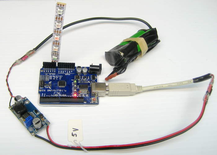 That low derived power supply bothered me. Was that diode not really a Schottky? I should at least be able to see some 0.3 or 0.4V pulses across the diode. Back to the good scope. Oh – to look across the diode and avoid ground problems, I’d need an isolated supply. Blessed with a nice shop, I had my usual 2P 18650 Li-ion with female 0.1″ header, found a boost converter with 0.1″ male header in and female out, set and marked for 5V (though I did check that) and a pigtail with 0.1″ male header in and USB old type B out for the Arduino end. I must have done something like this before. 🙂
 Looking across the diode, I saw pulses – at about 1.8V PP. Huh? Verified diodes were BAT85. Datasheet said 0.6-0.8V forward at 100mA. Something’s not right. Heat damage from soldering short leads? Tested another one of the diodes at 85mA (DC): 0.68V. Bridged that diode across the formally soldered in one, but still saw 1.7V data pulses. Derived power was still ~1.5V.
Tried +5 to boost derived power. LEDs worked, and data pulses at Din were back to ~4.7V. Looks like we basically had the Arduino output pin beating itself up with nothing but its internal impedance to limit current thru the (Schottky!) diode directly to DC +1.3V/AC ground via that big cap. Didn’t try to measure those current pulses, but I guess they must have been big.
Last ditch effort: With pulses potentially > 4V, that cap should at least eventually have gotten more charged than 1.3V. Were the other LEDs drawing so much it could never charge? Cut off top 4 LEDs, so cap only had to drive one. Same results, whether in intended config or with real ground. Oh well, Fail.
While writing this up, I thought I should read Tubular’s article (which I’d only skimmed before.) And I came across this “tip”: “Have a bank of “phantom white pixels” after the physical pixels. The large number of 1’s in the data helps boost the average voltage”. That makes a LOT of sense. A couple of lines of code later to init the library for 100 Neopixels instead of 5 and write RGB 0xFFFFFF to the extras, and it works! Even using another I/O pin as ground as originally designed!
![]() The duty cycle of the data sent out by strip.show() was tiny in the strandtest example I’d chosen. Here’s the difference between a 5 LED and 100 LED datastream at the + end of the cap. Those nice wide bursts haul the average DC up from ~1.2V to ~2.4V – enough to make the strip work! Tubular probably had code that refreshed his strip much more frequently than strandtest (which mostly sleeps, 20ms at a time) when he indicated it worked even without the “ghost pixels” to bump up the duty cycle and thus derived supply voltage.
The duty cycle of the data sent out by strip.show() was tiny in the strandtest example I’d chosen. Here’s the difference between a 5 LED and 100 LED datastream at the + end of the cap. Those nice wide bursts haul the average DC up from ~1.2V to ~2.4V – enough to make the strip work! Tubular probably had code that refreshed his strip much more frequently than strandtest (which mostly sleeps, 20ms at a time) when he indicated it worked even without the “ghost pixels” to bump up the duty cycle and thus derived supply voltage.
Made a little video clip of one LED changing colors. Soldered the other 4 back on and it still worked, but flicker with the camera frame rate made the video unsatisfying, so I went with the one LED version. It’s here.
Takeaway
If I’d read the original post more completely (and understood the importance of the “ghost pixels”!), I could have saved myself a whole day of messing with this. It then would have been the quickie I originally signed up for.
Here’s your next project
https://blog.hackster.io/control-and-power-a-16×2-lcd-display-with-only-two-wires-b4d4d0af9ed8?mc_cid=9af641ce39&mc_eid=ad1686030f