
 I’ve been using the Arduino ISP programmer sketch, an Arduino, and one of my mini shield cables as my AVR programmer for a couple of years now, and that’s been pretty satisfactory. There’s always an Arduino around, it works, and it’s essentially free. I felt no need for a dedicated programmer.
But when I ran across a USBASP knockoff on Ebay for $2.29 (and of course free shipping) I couldn’t resist. Unfortunately, it had the ‘other’ Atmel standard programming cable – the 10 pin version. Everything I have – including Tiny85 boards – is 6 pin. Fine – the cable shouldn’t be hard.
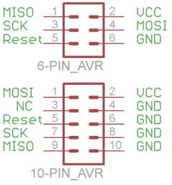
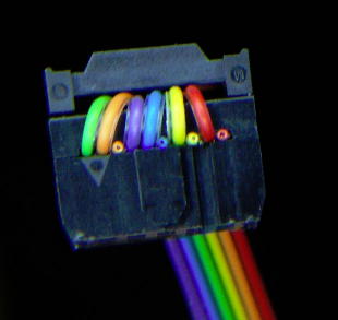 The pinouts of the two connectors are readily available. But it turns out there’s a really nice Inventable on making such a cable, complete with an excellent picture that tells just about everything you need to know. The author suggested using little scraps of wire to fill in the unused positions in the 10 pin header, which seems to work well. Warning: this pinout doesn’t work with this programmer! See update below.
My programmer came with a 10 pin cable, and I think I cut one end off and reused the connector for the 10-to-6 pin adapter cable that lives in the programmer now. That’s not a great idea, since the insulation displacement clips in those connectors are really designed for one-time use. But it was in keeping with the cheap programmer. And it works 🙂 The 6-pin end is marked with whiteout on pin 1 as is my custom.
But avrdude didn’t like it
Unfortunately, the first time I tried to use it with avrdude, I got this error warning:
avrdude: warning: cannot set sck period. please check
for usbasp firmware update
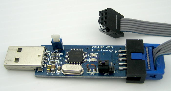
Fortunately, that’s an eminently googleable string, and Google did not disappoint. Many thanks to this nice article by Roger Clark that told me everything I needed to know. The latest code comes directly from USBASP originator Thomas Fischl’s site (thanks for the great work, Thomas!). I’m running usbasp.2011-05-28.tar.gz. The critical not-so-obvious tidbit is that there’s a jumper (JP2 on mine) that must be populated to reflash the ATMega8A. Interestingly, you program it over the same connection that it uses to program its target chips.
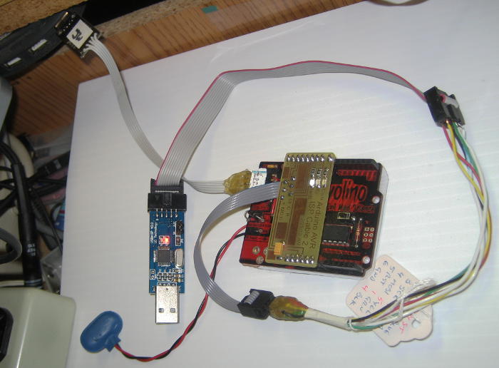 Of course you have to have an AVR programmer to program it. And I do 🙂 My old standby did a fine job of (re)training its replacement.
Once that was done (and the J2 jumper cut) avrdude stopped complaining, and the programmer seemed to work just fine. I reburned a bootloader on an Arduino, and verified that I could check the signature on a Tiny85. Great!
Not so great
While I was working on a hacked version of grbl for the W88 Shapeoko 2, I threw the new programmer in my bag since I knew I’d need it to burn grbl on the SO2’s Uno. (Grbl overwrites the bootloader, so every time you want to install a new version, you have to have a programmer. The grbl code is available as a hex file – which you need a programmer to install. It’s also available as a library that can be compiled and downloaded with the Arduino IDE. But that requires a bootloader, and you have to have a programmer to burn the bootloader. So you need a programmer no matter what.)
I pulled out my new toy, plugged it onto the ICSP header on the Uno and tried to burn a bootloader. Fail. Couldn’t even read the signature on the ATMega328P. WTH!? Fortunately I had another Arduino, and scrounged a programming cable from the first Thotcon badge stuff. That worked fine, so I was able to do the night’s grbl work. But what was wrong with the programmer? (It was my cable’s fault: See update.)
When I got home, I tried the USBASP clone on a couple of AVRs. It worked fine. Back to Google.
It’s a matter of speed
That ‘sck’ referred to in the original error warning message is the SPI clock rate the programmer uses to clock data into its target. And if the speed is too high, some chips won’t program (as was apparently the case with the Uno – but it wasn’t the Uno’s fault). It turns out there are two ways to change that speed with USBASP.
The first way is with yet another jumper on the programmer. On mine, it’s marked JP3. When that jumper is in place, the programmer runs with a much lower clock rate. It takes noticeably longer to program with it that way. But at least it works! Later observation showed that jumper slows the clock from ~1.5MHz to ~5KHz (!).
The other way is from the avrdude command line. The -B bitclock option (you know – the one it thinks you meant when you screw up trying to set the -b baudrate) lets you specify it directly in μsec. Avrdude gui avrdudess sets -B to 0.5 for 1.5MHz SPI clock and 20.96 for 32KHz. Looks like USBASP only supports specific clock rates, and uses the one closest to what -B requests.
Anyway, after I put in a push-pull switch for JP3 (you can see it in the picture above) and connected the pins, the programmer talked to the SO2’s Uno fine. (The slow clock jumper is not needed with a valid cable. See update.)
I’m sufficiently sold that I bought a second one (cost me $2.59 this time!) so I can keep one in my box at W88. Now that I know about JP2 and JP3, have the latest firmware and know how to make the cable, it won’t be hard to set it up as a reliable tool.
Update: Signal level warning!
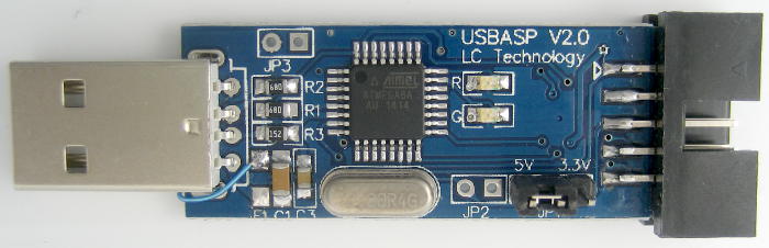
12/27/14 While trying to set up the USBASP to support PDI to reflash the 3.3V Xmega processor in my cool little $20 Xprotolab USB oscilloscope (see update), I ran across this excellent post by Ketturi Fox. He warns that when you change the JP1 jumper from 5V to 3.3V on a version of this programmer with Lcsoft Studio on the silk screen, it changes only the Vcc voltage on the output connector . It doesn’t change Vcc to the processor chip on the programmer, so it still puts out 5V logic levels – out of spec for most 3.3V chips!
My USBASP looks otherwise identical to his, so I looked at the SCK output level with JP1 set for 5 and 3.3V. Sure enough, the output levels were 5V either way (though the Vcc voltages did follow the jumper as expected).
In addition to patched code for USBASP and avrdude for PDI support, KF kindly 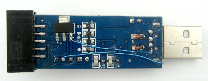 provided a fairly simple fix to the output levels: run the onboard proc from the JP1 output by removing a fuse, adding 2 air wires, and cutting one trace. I applied that fix to mine, retested the output voltage levels, and they now follow the 5V/3.3V jumper (as they should have in the first place). Thanks, Ketturi!
So now my knockoff USBASP is even better. Hmm – guess I better add that mod to the W88 programmer when it comes as well.
Update: W88 version is slightly different
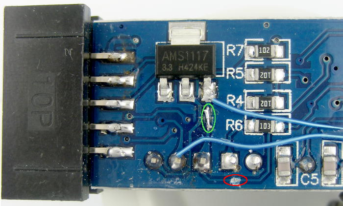 12/30/14: The new one arrived today and I did the mods. Although the top silkscreen said the same thing, the actual board layout was at least slightly different: The trace feeding the regulator and the +5 side of the voltage select jumper that needs to be cut comes around the bottom edge of the board. It’s circled in red. No biggie; it just provides another opportunity to be righteously indignant about somebody changing something without changing the version number. 🙂 (The cut/patch circled in green was a mistake – oops.) Otherwise, the firmware update worked, the output signal levels (as well as Vcc) follow the jumper, I made up another 10 pin to 6 pin cable, and all seems to be fine.
Update: Corrected cable wiring
My original programmer – with my original 10-6 pin cable – didn’t work with an Uno. It was my fault: the cable pinout was bad. The very nice Inventables article chose to pick up GND from pin 4 on the 10-pin side. That doesn’t work here, as they’ve used pin 4 for something else. Here’s the pinout I ended up with – which picks up GND from pin 8 and works. Using pin 10 would have worked as well.
6-pin    10-pin
 1  MISO  9
 2  VCC   2
 3  SCK   7
 4  MOSI  1
 5  RST   5
 6  GND   8
 After I made up a new cable with that pinout, it worked on the Uno at 1.5MHz just fine. I still need to make up another cable with the correct pinout for the W88 programmer. (Done.) The real question is why the first cable ever worked at all.
I found this schematic for a knockoff USBASP in a nice user manual put 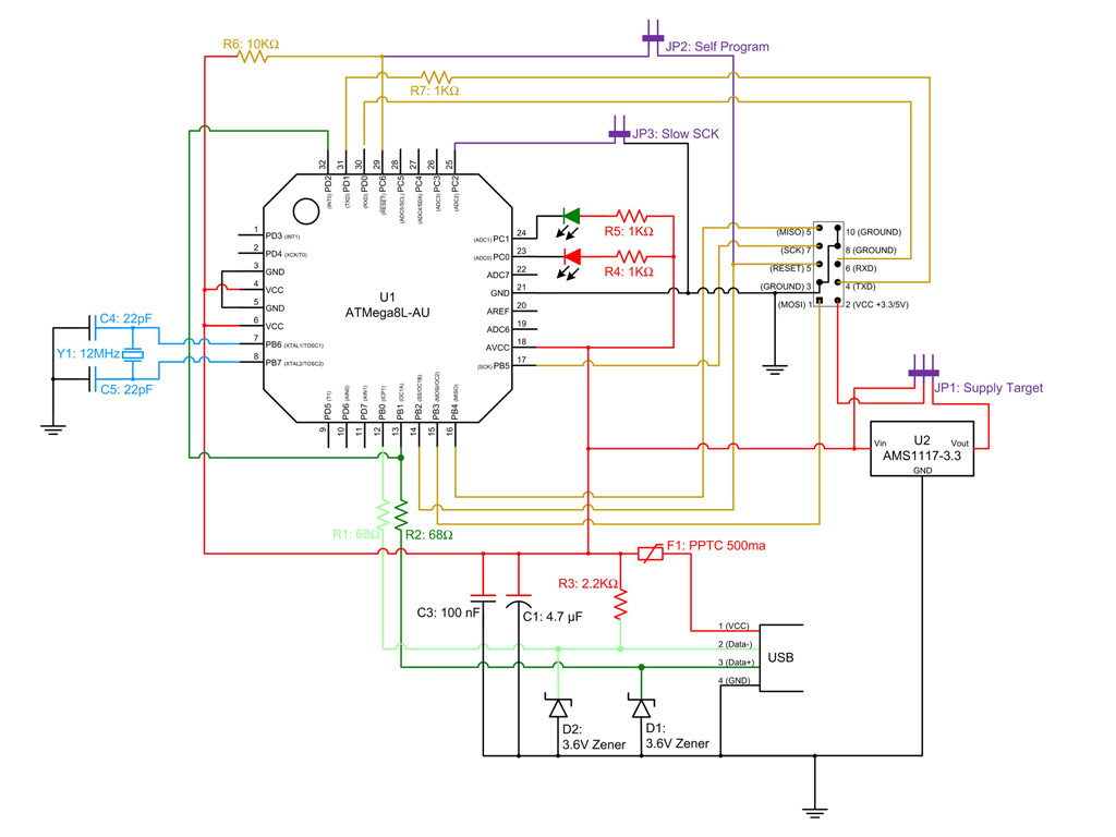 together by protostack.com for a USBASP they sell. Hats off to them for providing actual documentation. That’s a nice way to take advantage of low priced Chinese stuff, add value, and provide a product. I’m not certain this is exactly like the one I have, but it has the regulator and voltage select jumper, and pins 4 and 6 ohm out appropriately to CPU pins 31 and 30, so it’s pretty close.
Update: PDI programmer and more cable stuff
The firmware update nag messages for my Xprotolab Plain oscilloscope caused me to find Ketturi Fox’s excellent page on upgrading a knockoff USBASP for that purpose. The AVR Xmega processor in that scope doesn’t support the good old ICSP programming interface, instead requiring the Programming and Debug Interface (PDI). I boldly tried KF’s plan, but it involved 3 separate steps:
- Update USBASP firmware to support PDI
- Update avrdude to support PDI (at least on USBASP)
- New cable for PDI
He provided source and strongly recommended recompiling both the USBASP and avrdude code (more trouble than I was willing to take), but provided binaries for both (with warnings). I updated my USBASP (but not the W88 one), and it still worked for ICSP, so I hoped that was OK. I downloaded his avrdude.exe, and despite his warnings that it had been compiled on a 64 bit machine, it seemed to work on my 32 bit machine for ICSP. And how hard can the cable be? I made up a cable from scraps from the ribbon cable box.
It didn’t work with the Xprotolab’s Xmega, with a not very helpful message about the target not responding. I pouted and put it all aside.
While trying to figure out why the USBASP wouldn’t work with Unos (via ICSP), I stumbled upon evidence that the ground connection was somehow bad (maybe it worked if a scope ground was connected?). Chasing deeper, the pin 4 on the 10-pin USBASP interface that the Inventables article used for ground is one of the serial lines, both in the Protostack schematic and Fischl’s original schematic. (What are those serial lines used for? This post on avrfreaks indicates “for future implementation”.)
So my (first) cable is bad. OK – I verified that pin 8 really is ground, and set out to redo the 10-to-6 pin ICSP cable using that ground pin. Unfortunately, while disassembling the 10-pin end (originally from the 10-to-10 cable that came with the programmer) I broke a part. Digging around in the ribbon cable box I came across a 10-pin connector with a suitable length of ribbon cable already attached. Great! But on closer inspection, that ribbon only had 9 wires – pin 10 was empty. Since I didn’t need pin 10, I went ahead and made a new cable with that as the 10 pin end and a hand-made funny-wired 6 pin on the other end (since I stock 6 pin connectors). That cable worked (including with Uno). So I’m in good shape for ICSP.
But then it occurred to me that the cable scrap I’d made the PDI cable from came from that same box. Checking, sure enough – the PDI cable only had 9 wires! I’d missed that, 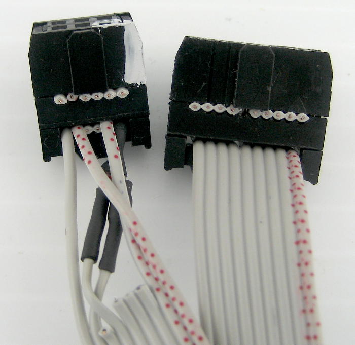 and while making up the special PDI cable, I counted from pin 1 for some wires and from “pin 10” for others. Pins 7-10 were off by one!
(After another dumb mistake in counting wires from the pin 10 end) I moved the top 4 wires over by one and lo and behold – the hacked avrdude/USBASP could see the XMega32A4U on the Xprotolab scope via PDI! I burned the updated firmware from Gabotronics, and the upgrade nag messages stopped. I won! Much of the payoff was that I could finally put the scope back in its box and put it away. One more half-finished project not staring me in the face!
Awesome that you too could get usbasp work as PDI programmer! I too found out the hard way that pins 4 and 6 are not ground but serial, forgot to mention that, whoops…
Good thing that you got it sorted out in the end.
Wow – thanks for the reply, Henri! I’m honored. 🙂
I’m glad the PDI stuff is running, too. It was frustrating for a while there when it wasn’t: I didn’t have a working PDI programmer or any other XMega chips to try to narrow the problem down. I’d accidentally plugged it into my XMega scope with the Vcc jumper set for 5V (OK, more than once 🙁 ), and while the scope still worked, I didn’t know if I’d fried some part of the programming stuff. I was just about to send a note out to our local hackerspace to ask if anyone had a PDI programmer when I stumbled on the cable stuff above. So at least this little 32A4U survived a couple of brief encounters with 5V. I’d never intentionally do it again, tho!
Cheers!
Nice post! I wish someone use TX/RX in the USBasp firmware some time … I would love to use USBasp to program the target device (now only ATmega, not ATXmega though) then via TX/RX the target can do serial communication “relayed” via USBasp through the USB port of the PC with a kind of serial terminal program running on the PC 🙂 I don’t like too much the solution that I need to plug USBasp and also a TTL serial … serial … serial/USB … PC cable/converter chain to another port of the PC to be able to communicate with the target device then, especially because my notebook only have a single free USB port (and as far as I see, USBasp does not work in an USB hub ….).
Thanks for the comment, LGB. I was also surprised to find the hidden “for future use” serial pins on the USBASP, but not curious enough to pursue it until your note. A quick search found this and this. I haven’t tried them, but I’m hoping you will and will post back and tell us all how it works out. I agree having “free” serial connection thru the programmer would be great!
I’m not sure what your problem with a hub is. My main PC is a few feet away from where I sit when using it, so I have a little 4 port (powered) USB 2 hub permanently mounted near the keyboard. I’ve used my USBASP programmer with that many times, and never had a problem. (Using the neat $20 Xprotolab USB oscilloscope doesn’t work well thru the hub, but that needs pretty high bandwidth, so I have to plug it directly into a USB port on the PC.)
Let us know how it goes with the serial mod!
Jim
Honestly, I’ve never tried an USB hub, since I haven’t got one 🙂 Just I remembered (maybe I was wrong!) that I had read somewhere: USBasp won’t work over an USB hub, because the limited USB implementation (like it does not know about suspend, etc either). However, I can be wrong here, if you say it works, I will get an USB hub to solve my “too few USB ports” problem then 🙂 I must admit I am lame with USB, especially the USB software stack used by USBasp, I am not so in with MCU programming yet, to be able to understand the details, I’m afraid.
Your findings look interesting! If I have some time (well …) I’ll try the USBasp-tty hack. The client software can be a problem, as I don’t have (and haven’t ever had) Windows, and the software seems to be quite Windows centric C source. Anyway, I have the hope that I’ll manage to hack some light terminal program together (with the help of the Windows source) which is usable with Linux then.
Another approach was this firmware, which does “console” over the SPI bus, which is also interesting to think about. Unfortunately, currently it does only support reading the communication buffer on USBasp “pushed” by the target (as being that SPI master then) over SPI, so it’s not bi-directional communication yet.
Since this was written, it now supports the TPI programming protocol as well. (Maybe not strictly since as the firmware was circa 2012)?
Thanks, Matt – I didn’t know that. I’ll try to remember that next time I need to program something that (only) supports TPI!
Hello…
Is there some “latest” firmware for that. I can’t manage to program xmega128a3u
(Sorry for the tardy approval.) I assume you mean latest firmware for USBASP. The only firmware I’ve used is what I found on Ketturi Fox’s site https://ketturi.kapsi.fi/2013/05/programming-xmega-with-usbasp-avrdude/ .
Done it slighty differently, I’ve kept the fuse in place and cut the trace from C1 to C3, soldered a wire from the fuse to Vin of the LDO and from the middle pin of the jumper to R5 (could have been R4 or R6, just easier for routing).
Here’s a picture http://imgur.com/a/l2t6O
Nice mod (and picture!). Of course due to subtle differences in layout between (like-numbered!) versions of the board, I’d suggest to anyone who wanted to try this to carefully trace out the paths on their board to make sure they’re doing what they want to do rather than just copying either of our hacks.
Nice article. I have just ordered this particular cheap AVR programmer as it’s the only one that I’m aware of that theoretically has a 1 Amp regulator. Hoping that there’s been a revision where it’s not necessary to mod it to re-programme 3.3V Arduino Pro Minis to run eForth. I anticipate that on a 64bit Windows 10 platform to avoid driver signature problems I’m going to have to install Zadig and select libusb. I’d be really interested in any updates or suggestions.
Hi Peter,
Yeah, it would be nice if newer versions correctly managed the voltage for the logic as well as Vcc, but I’d sure look at the voltage levels out – say on SCK – to verify that hope before I hooked it up to anything I cared about! Post back if you lucked into a version that does it right.
I’ve had libusb on my main Win 10 machine for so long I don’t remember how I installed it. There is a copy of Zadig on the machine, so although I don’t remember it, that might have been what I used. But I do recall having a lot of trouble getting libusb on a new Win 10 laptop. It would work with some things but not others. Maybe I’ll try Zadig and see if that helps. Thanks for the reminder!
Jim