
 My water meter (with a Neptune T-10 encoder) is connected to an external RF transmitter (a Neptune R900) to allow drive-by meter readings. Great! I’d like that data for my home monitoring system. (The bottom line is here.)
That meter has since been replaced with a Mach 10 using E-coder Plus protocol. Decoding that one is described below; see Update 9/13/17.
Can I listen in?
 There’s a cool 900 MHz utility meter monitor tool mentioned in this Hackaday post. Unfortunately, while it can receive the transmissions from an R900, it can’t decode the data (yet). I sent a note to Greg at gridinsight.com and asked if I could help with development of the R900 code, but what’s left would involve crypto stuff I know nothing about. Nice try. I guess I’ll have to try to eavesdrop on the data going from the meter to the transmitter.
The 3-wire connection between the two seems to consist of common, data (from meter to transmitter), and clock/power (from transmitter to meter). The transmitter apparently polls the meter periodically by sending a string of clock pulses to it. The meter responds by putting (usage) data on the data line, clearly clocked out by the clock pulses from the transmitter. I can see both the clocks and the data; now I just need to decode the data so my home monitoring system can use it.
The encoder
 The water meter seems to be cleverly designed with a separate “encoder” unit magnetically coupled to whatever it is that actually moves with the water flow inside the meter body. That encoder, which can be replaced on the fly, contains the clear plastic head with 6-digit odometer style counter, a big hand with a calibrated dial for the least significant reading, and an uncalibrated double ended red “spinner” that shows flows too small to be seen easily on the big hand. The 3-wire interface is part of that encoder. While it might be possible to harvest a little energy from the water flow, I think the encoder has no internal power.
Apparently (my inference) the device at the other end of the cable (here, the R900 battery-powered transmitter) polls the encoder by sending a stream of clock pulses to it. The encoder extracts enough power from the 5V logic level clock stream to allow it to reply on the data line with the current values of the odometer counters. An interesting feature of this mechanism is that the polling device always gets the complete total usage reading – not a delta. Thus the reading is essentially guaranteed to be accurate.
A little more detail
From the product information on the R900, while it sends a 900 MHz spread-spectrum RF burst with the “latest” usage data every 14 seconds, it only polls the meter once an hour. (Thus the quotes.) While I’d like to just be a non-invasive listener, I’d really like more granular data. I suspect, but haven’t tried yet, that if I inject a suitable series of clock pulses at times of my choosing (maybe every 10 or 15 minutes?) the encoder will respond to me just like it does to the R900.
Of course it would be very inappropriate to impose my clock pulses on to the R900’s clock driver output. One possibility would be to put a (probably Schottky) diode in series with both the R900’s clock output and mine, hoping the 0.3V lower voltage level on the clock line would still allow the encoder to respond reliably.
And then there’s the interesting question of how the unsolicited data transitions caused by my clock pulses might affect the R900. I suppose if I wanted to be very polite about that I could interrupt the data line to the R900 with a relay so it would only hear the data it expected. But that’s a way out yet.
Decoding the data

 Back when I hoped to be really non-invasive (never disconnecting the original wires), I made up something with spring contacts to connect to the screw heads of the 3-wire interface. That gave me a nice wire coming out with all 3 connections I could play with.
I connected the wire to my USBee SX logic analyzer (the first time I’ve used it!) and set it for 1 M samples at 1 μs/sample (lowest number and lowest rate offered). I set a trigger for lo-hi edge on one of the clock/data lines (I didn’t know which) and left it for a while. It triggered, and I looked at the data, but it didn’t make any sense at all. After some head-scratching, it looked like the wire I’d used for common (black – duh) was in fact one of the clock or data lines. Trying again with green as common, I got (what I think to be) a good capture. A nice stream of clock pulses on one line (black) and some kind of data on the other (red). Maybe 0.26 sec of data out of the one second capture, but I can ignore the silent times. I’m home free!
Well, no. While the data transitions always occur right on a clock edge, some are on a rising clock edge, some on falling.
 Looking at a larger scale and starting right after the very first rising clock edge, the same pattern appears on the data line 6 times in a row. (Picture on right is just the first instance of that pattern.) Counting a clock pulse as one hi time and one low time, that pattern takes just 16 clock pulses. That’s a nice number. Unfortunately, looking past that initial (sync?) pattern, there are “blips” (I don’t know any appropriate word) of data – between a rising and a falling edge, but not
  necessarily in that order – that are only 1/2 clock pulse wide. (Is that really a bit time?) There are both low blips (falling edge followed by rising edge) and high blips (rising -> falling). POSSIBLE CLUE: (it looks like) all high blips occur during a high clock half-cycle and all lo blips occur during a lo clock half-cycle. Here’s more:
Hmm – all the one-half-clock-pulse wide blips I could find start on a clock falling edge and end on a rising clock edge. Also, all the longer N-and-a-half clock width blips are adjacent to a half-clock blip. I don’t understand the implications of all that – it’s just some random observations.
I could really use some help figuring out the protocol – at least step zero to read bytes from it. If anybody wants to play, the USBee binary capture file is here: water2ulb.txt. You’ll need to rename the file to water2.ulb. The USBee SX logic analyzer code – which will run in demo mode without the USBee module plugged in – can open that .ulb file so you can root around in it. You can freely download the (Windows 32 bit) logic analyzer code here: http://www.usbee.com/sxdemo.zip (more versions here: http://www.usbee.com/download.htm). Fifteen second GUI lesson: left/right mouse clicks zoom in/out; click & drag to pan; left/right clicking in “Cursors” bar sets “X”/”O” marks; click something in “Cursor Insta-measure” and mouse over the data for some tools.
Update 9/4/12: After staring at it for a long time I noticed a pattern: There’s always a 1/2 clock cycle lo “blip” on the low half of every 16th clock cycle, always followed by a high blip of either 1/2 or 3 1/2 clock cycles. And those are the ONLY instances of 1/2 cycle nonsense. Otherwise all data line transitions are reassuringly on hi->lo clock edges. Those statements apply to both sections of the communication capture: The first ~500 clock cycles of 50% duty cycle and 0.3ms width, and the last ~250 clock cycles of 33% duty cycle and 0.42ms width. (What’s that about??)
So the half-cycle stuff is clearly some kind of frame delimiter. But with 15 clock cycles of usable data time per frame, the bit encoding is still unclear. More head scratching ahead.
To avoid conflicts with my someday higher frequency polls and the polls from the R900, I needed to know how often the R900 actually polls. I set up an Arduino to look for lo-hi transitions on the clock line and timestamp them. (It sleeps 1000 ms after it logs a transition to ignore the ~0.25 seconds of actual data.) The R900 is quite uniform in polling about every 3030 seconds.
Even more interesting is that the polls are sometimes repeated after a second or few, up to 6 times in the day or two I’ve been logging. Most polls are not repeated. A first guess is that a repeat poll is sent when some kind of checksum fails.
Update 9/6/12: It occurred to me that my simple assumption that the reader provides a series of clock pulses and the encoder drove the data line might not be completely right. (Especially in light of the change in clock duty cycle after the first 500 or so clock pulses.) To see who was really driving the bus (?), I thought I’d isolate the two sides with Schottky diodes oriented so the R900 power/clock could get thru and the data line high states from the encoder could get thru. (Two diodes pointing in opposite directions.) I’ll spend 2 more channels of the USBee SX and monitor on both sides of both diodes. I’m hoping the logic thresholds will let me see if there is any difference on the two sides of the diodes, indicating a more interesting story than I originally assumed.
 The only Schottkys I had were SMT, so I sliced two insulating slots in a bit of scrap copper clad, soldered the diodes on, and set it up so it would be easy to insert inline in the black (clock/power) and red (data) lines. (Green is common and will remain connected.)
 I didn’t want to interrupt an R900 poll (though I don’t think that would cause any real trouble), so I needed to know when to expect the next poll. My Arduino sketch logging time between polls was still running, but it didn’t tell me how long ’til the next poll. I added a Serial.available() check so any keypress will print time since last event (and, assuming 3030 secs between, estimated time ’til next). Now I know how much time I have to remove my spring contacts, rewire the cable to the R900, reposition my spring contacts, and set up the USBee SX.
Grumpf. The PC software had somehow lost contact with the USBee module and wouldn’t run and capture. I had to shut it down, unplug module, replug module, restart software, and set up for the triggered capture again. In doing that, I missed the poll event. Grumpf.
And then several more misses. Can’t find the USBee help files – bad link on their web site!
OK – got a capture. (USBee setup: set CLK input so you can change Capture on TRIG to hi; set CLK back to output; set 1st 2 cols on clock sig to lo, hi; click Acquire.) Clock is identical on both sides of the diode. Good – no funny business from the encoder (like providing the clock!). So I have to believe if I injected a clock pulse stream, I’d elicit data. But the data line is not identical. Data is clearly driven on the encoder side. Unfortunately the signal on the R900 side goes high and stays high. Very high input impedance? Anyway, I don’t think the R900 gets the data. Its clock stream extends way longer than normal. Jumpered around the data line diode. New capture much better, but not quite like first one. That capture is water4.ulb.
The Arduino monitoring polls also saw re-polls until I jumpered the data line diode, then R900 got data first poll. The bad news is that now I still can’t tell if the R900 ever writes on the data line.
Encoding details
 Update 9/9/12: OK – I think I’ve won. The apparent re-polls from the R900 when the (weak-drive) data line was connected directly to an Arduino input caused me to add a simple buffer to reduce the loading on the encoder’s data line. That seemed to help. After I fixed dumb bugs in my code, the Arduino started getting data. Then I replaced the function that waited for a clock edge with code that toggled a bit so the Arduino provided the clocks. Once I could generate my own clocks, I made a lot faster progress than back when I had to wait 50 minutes for the R900’s next poll!
And that let me figure it out. Here’s how the data is encoded:
 The (brown) clock is regular, with a period of ~300 μsec. The basic bit time is from clock falling edge to the next falling edge. Five bits of data (red line) are shown – pretty obvious.
There’s a frame delimiter (Frm) consisting of a half-cycle of low (starting on clock falling edge) followed by a half cycle of high (starting on clock rising edge). This frame mark (from the register encoder) occurs regularly every 16th full clock pulse. That gives us 15 bits of data per frame. When data bits are being clocked out, a data line transition is never allowed on a rising edge, making the frame mark completely unique.
 Looking at the “sync” frame, here’s how the data is decoded. After the frame mark, we take blocks of 4 bit times and express them in binary. With LSB first, the bits in each nibble are reversed, and all the nibbles are reversed. There are only 15 data bits, so the most significant bit (X) is missing; we assume it’s a zero.
Very interestingly, the only nibble values that I’ve ever seen are 4 and 7. Now, for reasons I don’t understand, we assign a nibble value of 4 to be logical “1” and nibble value of 7 to be logical “0”. The sync frame above then has the logical value 1110 – or 0xE.
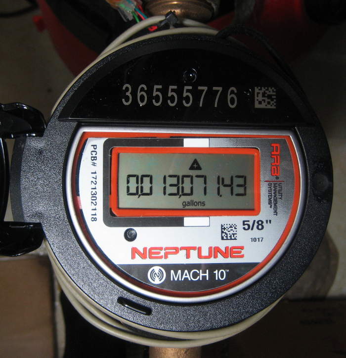
The actual usage data is expressed in BCD, one digit per frame. That 0xE sync value is reassuringly not a valid BCD value. Along with and bounded by a LOT of sync frames, the most recent capture has four consecutive frames with values of 7477, 4774, 4774, 4777. Converting to  logical and expressing that BCD as decimal, that’s 4998. This meter shot, taken a week or two ago shows a close, but lower value in the high 4 dials. Right after I took that capture, the meter read 4998. (Update 9/11/12: The meter just rolled over to 5000 (in the hi 4 digits) and a poll from the Arduino produced the same value. I declare the decoding described here to be correct.)
The bad news is that it provides terrible resolution for my needs (like verifying that the watering system is working), although perfectly adequate for the city’s billing purposes.
One shred of hope was in the two phases of the R900’s poll, with different duty cycles. Might that second, 33% duty cycle poll elicit data from those lower two wheels and maybe even the big red hand? I found an early R900-clocked capture and manually decoded the data. Nope. Same patterns and same data as the 50% duty cycle poll. Bummer.
A few more observations about the whole data sequence. Starting from the clock line going from 0V to 5V (rising edge), we have the second half of a frame marker, followed by 6 frames of the 0xE sync pattern. Then we have 4 frames containing the (most significant) meter usage wheel data, 5 more frames of 0xE, then one frame of 0xF. Then the whole pattern repeats. The R900 poll sequence provided 300 μsec 50% duty cycle clocks for: 6 0xE, 4 data, 5 0xE, 1 0xF, 6 0xE, 4 data, 5 0xE; then 424 μsec 33% duty cycle (1 lo, 2 hi) clocks for 1 0xF, 6 0xE, 4 data, 5 0xE.
I tried 100 frames’ worth of clocks and the pattern of 6 sync, 4 data, 5 sync, 1 0xF just repeated and repeated. And no checksums – My earlier guess about a checksum fail was wrong. I guess the data integrity check is just to watch the data for more than one cycle and make sure it’s the same.
The bottom line is that while this was an interesting reverse engineering project, the results are not useful at all to me. I’ll just go back to my optical telescope. <sigh>
Final Arduino code to generate clocks and read data is here. Update 1/17/20: Very sadly, I think the code linked above is all I have on the Pro Read. There’s a comment that the original code was lost, and I’ve dug thru all the archives I can find, and there’s no trace of that code. I guess when I realized it wouldn’t provide the data I wanted, I really just gave up. Can’t imagine that I would have deleted the code, tho.
Of course Bob’s github repo is still there. I may get some clean code helping Jean-Marie get his T-10 working, and will post that.
Earlier attempts
I’ve wanted water usage data for a long time. I had a temperature sensor on the incoming water line that could very crudely sense when water was flowing (with better luck in winter when incoming temp was farther from basement temp). I considered taping a mic to the pipe and looking for noise. But the water meter was the obvious source of the data. While I seem to have gotten over it, at the time I didn’t want to hook up to it electrically. But maybe I could get the data optically.
I built an optical telescope looking at the spinner, and even got it to work and calibrated it in gallons used. It ran for a while, failed for a while, got fixed and ran a little more before final failure. Details are here.
Update 9/13/17: New meter coming!
 I just got an email from our town (Elmhurst) saying they’re about to replace all residential water meters with new ones. From the picture they included and some words in the notice, it looks like it’s a Neptune Mach10 ultrasonic time-of-flight meter. Two “wet” ultrasonic transducers measure time of flight of acoustic signals with and against the flow, computing the flow speed from the time difference. No moving parts, 20 year sealed battery, and WAY finer resolution: 0.1-35 GPM.
It speaks E-Coder Plus protocol, presumably with the full 9 digit value of the counter. It looks like the communication is still 3 wires (green still ground), so Bob Prust’s Arduino code should still read it. It looks like the implementation here will be meter/encoder inside the basement where the old meter was, and a (new) RF900 MIU outside.
Also very interestingly, they claim there will be a web portal for users to see their usage in finer detail than what we get on the bill. Don’t know how good that will be yet.
Also interesting, I won’t have to feel guilty about not getting my old optical telescope working any more. 🙂 And I wonder if I can piggyback installing an electric whole house shutoff valve along with the meter installation. I mean, as long as it’s all disconnected…
Installation some time between October and March 2018. I’ll post more when it’s installed.
 Update 2/22/19: Several months ago the city installed the new meter. With some sadness, I didn’t have my act together enough to install the Water Cop shutoff at the same time.
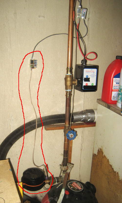
I haven’t even touched the new meter to try to get any data from it. While that’s not out of the question, I’m leaning more toward installing my own flow meter in the section of pipe I’ll have to plumb in to install the shutoff. More to follow.
Update 9/4/19: I’ve tapped into the lines to the R900, and gotten a couple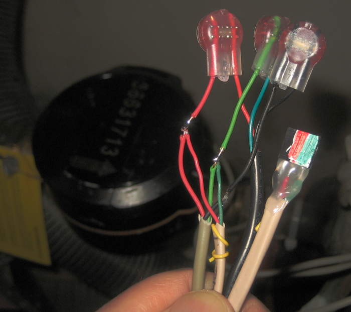 of initial data captures. No insights yet. Protocol (which is said to be E-Coder) is clearly different: no nice frame markers, no obvious data
 repeats.
To look at the data in a more convenient manner than the ‘scope trace’ display, I got the USBee SX to play the clock and data back and wrote an Arduino sketch to decode it (as synchronous data against the clock) and display it in hex. Of course with no clear frame delimiters, the ~45 bytes of data could be arbitrarily bit-shifted. More to follow.
Update 10/6/19: 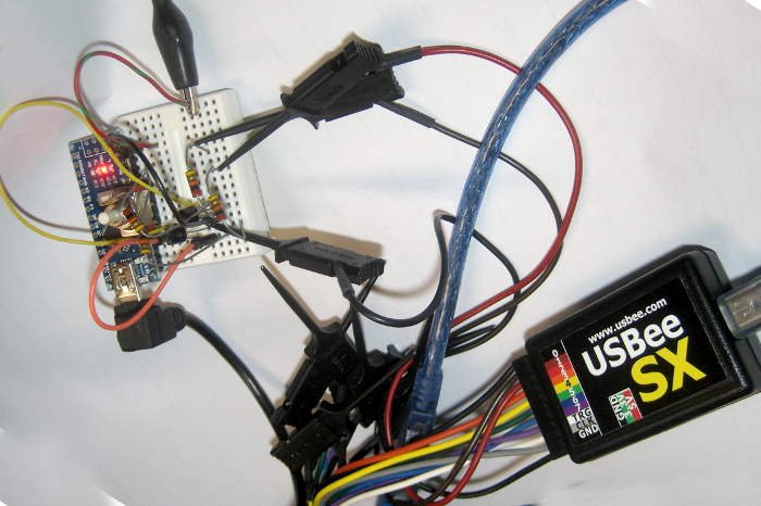 Woo hoo! I just played back a USBee SX capture from the meter to an Arduino sketch inspired by approaches in Bob Prust’s E-Coder code and got strings back with my meter’s serial number and water usage values! There’s some more work, but the decoding is resolved.
I think I’ll just “listen in” to data triggered by the R900’s once-an-hour polls. I’d like a little finer granularity, but this way I don’t have to cut any wires. I’ll include little one transistor buffers to minimize the load on both the clock and data lines.
Clock half-cycles are ~400 µsec, so trying to service both the Neptune capture and polls from the HA system might be touchy. I could use interrupts to sense the clock transitions, but I hate to just spin for the 200 µsecs until I read at mid-clock phase. Maybe just ignore the 485 net polls when I’m reading the meter: I think the retry cycles built into the 485 net protocol are slow enough to survive missing one poll because I’m busy. We’ll see. More to follow, but I was just really delighted to get the first Neptune data!
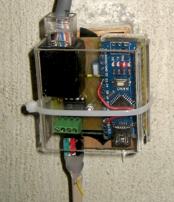 Update 1/13/20: Oops – I guess I haven’t updated this for a while 🙁 From file timestamps, it looks like I got the Neptune decoder working and integrated into the home automation system ~10/21/19. Here’s the Arduino based 485 net node that connects to the meter.
 And here it is in its new home.
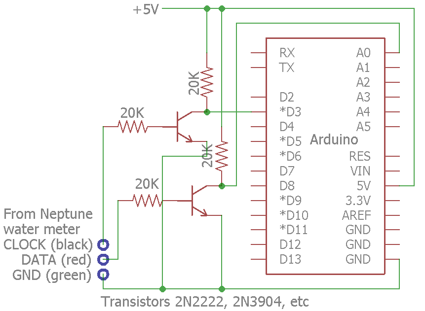 Pretty, but not very helpful. Here’s the schematic of the simplistic interface to the meter. The 20K input resistors were my attempt to isolate my stuff and make it minimally visible to the official meter/radio system. Seems to work.
I did end up with an ISR to read the meter input. In an embarrassing bit of misdesign, I interrupted on the wrong clock edge and fretted about having to put a 100μsec delay in the ISR for data to settle. (Generally a serious no-no, but it turned out I could get away with it due to an extra level of interrupt buffering I didn’t know about. Ugh.) After I interrupted on the correct clock edge, the data was already good, no settling delay needed. Dumb, but cost a lot of time. I did learn stuff, tho. 🙂
The decoding logic was from Bob Prust’s code. I reimplemented it because my hardware was different from his, but his base logic is good. I spoke with him and he said he’d be happy to have me commit a new version to his github node. There it stopped – I got busy and never put my code up. I’ll do that Real Soon Now. Thanks to SZaf for the gentle reminder. 🙂
(It turns out the critical paths of this and the new Water Cop house water shutoff valve got comingled, as there was only one drop from the 485 net near by and new cabling was required before they could both run. It’s all done now, and I can shut off the water to the house remotely (or via cron). Hmm – I guess I should write that up as well.)
Update 2/3/20: While I still plan to submit my Ecoder Arduino code to Bob Prust’s github repo, I’m out of town and can’t test stuff. But I did at least want to post candidate code here temporarily.
Here are two versions, one using an ISR and the other not. Both connect to my Mach 10 driven by an R900 using the buffers above, and output ASCII meter data. They should be basically the same. Neither is exactly what is running at home, as that’s co-mingled with ugly stuff to talk to my RS485 HA network. Change filenames from .txt to .ino.
I have considered a web cam pointed at the meter, and some sort of OCR software.. Sounds like a lot of trouble though.
Pingback: Optical interface to water meter | Jim's Projects
Very cool; good job! I wish I’d had them put an outside transmitter on when they retrofitted mine (mine has the transmitter indoors – I’m not all that edgy about RF, but having it outside would be nice, with the added benefit of having wires to tap into!)
Is your meter and transmitter one monolithic blob or is the transmitter wired on, but just located indoors?
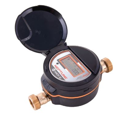
It’s monolithic sadly. Like the one in this image.
What’s really frustrating is that this thing has a lot of smarts; I just can’t get to it:
http://www.edcheung.com/automa/water.htm
Just thought you might be interested in the above website (not mine).
It describes a method using a hall effect sensor to bypass the meter mechanism and simply measure the rotating magnetic fields from inside the Neptune meter.
This provides a much higher resolution than the default interface.
Plus it has the benefit of not interfering with, or even connecting to, the wireless transmitter.
Hi Peter,
Nice job by Edward. Thanks for the link!
I was aware that there was magnetic coupling in the meter; sensing that was in fact the first thing I tried. Unfortunately, there’s about 3 amps of AC going thru my water meter (!?), and the 60 cycle magnetic field from that so thoroughly drowns out what I could pick up from the moving magnet in the meter that I gave up. I made some serious attempts to null it out, but failed. Filtering wouldn’t work either because at high flow the fluctuations from the magnet could be around 60 Hz. (There was a little comment about it in this post.)
It was an interesting moment when I first put an Amprobe around that pipe! Of course I tried to figure out why that current was there, but failed at that, too. I did get far enough to be fairly convinced it wasn’t a wiring problem in my house – but rather a problem in a neighboring house sharing the same power transformer. I suppose I should revisit that some day.
IF you have 3 amps of AC (or even DC) going through an underground pipe, methinks you ARE doomed to that pipe failing through electrolysis.
Unfortunately you’re probably right. It worried me a lot when I first found it, and I did about as much troubleshooting as I could from here and couldn’t find any reason for it. I think a possibility that came up was a fault in the ground/neutral connection in the panel of a neighbor who shares a transformer, but I wasn’t willing to try to extend my troubleshooting to his house. 🙁
…. FELLAS !! … the neutral from the utility provider is not right !! … does the lateral pass thru trees between the road and the house? That’s the first look !! You should NOT be getting any current thru your plumbing !!
Jim,
Your hack may be incomplete. From my understanding, the account number (meter serial number(?)) should also be included in the read. This to tie the reading to a specific meter. I wonder if there is a command sequence from the uP that is necessary to fully implement the protocol? Incidentally, I understand the Sensus protocol is also known as UI 1203. This is some form of (unpublished) standard.
Interesting comments, Sam – thanks! In all the captures I’ve looked at, I’ve never seen anything but data polls. Of course that certainly doesn’t mean that serial number polls don’t happen. I guess it doesn’t argue that there couldn’t be a serial number poll command/mechanism, but the fact that there’s no command for the data poll – just start sending clocks – raises the thought that the protocol looks too dumb to have any other commands.
Of course maybe the 5 or 6 bytes of 0xE I’ve attributed to being sync bytes are really the serial number, and my meter happens to have an unusual serial number that happens to encode to 5 or 6 bytes of 0xE. Seems kind of unlikely, but without more information (protocol details or observations from other meters) it’s hard to know.
If there is such a serial number poll command/mechanism, it’s quite plausible that when the R900 first starts up – maybe after getting a new battery? – it polls the meter encoder for a serial number and then just remembers it. No need to ask again. But I guess I’m not quite bold (or curious) enough to open the R900 and pull the battery (or look for a reset switch) while logging the data from the encoder. 🙂
Also plausible would be that the commercial account mapping is between the account and the R900. That device has a 10-digit serial number, and could very easily include it in every transmission. And I saw reference in some Neptune doc to a 10-digit number in every transmission from an MIU (Meter Interface Unit). Maybe the same number?
My water bill shows an 8 digit number as “meter number” which matches a number in the cast bronze housing of the meter. I doubt that there’s any way for the “encoder” part to be able to know that number (unless it was hard coded in by switches/jumpers/links when the encoder was installed on the meter housing).
I ran across mention of the 1203 protocol in my research, too. While I thought finding the details of that protocol might help a lot – and I tried to find it (but failed) – I seem to recall only reading that is was very similar, but not necessarily identical to the Neptune protocol. If anybody reading this happens to have a copy of that protocol, I’d love to see it!
Jim
Jim,
You’re probably right that Neptune protocol not identical to Sensus. As I understand it, the meter number must be hard coded into the meter electronics. Otherwise, possible to move interface electronics between meters possibly resulting in chaos. I too have had no success in acquiring UI 1203 protocol. Will keep trying, though!
Jim,
If monitoring and/or recording water flow is your end-goal, you can do anything you want on your (the customer) side of the meter at most water utilities. You have indicated that you have a basement with the incoming water line, this would be an easy access point to the water line. There are a variety of flowmeter devices and sensors here: http://www.omega.com/prodinfo/flowmeters.html. You could then get resolution suitable for your purposes.
Interesting comment. I’m very quick to mark commercial comments as spam to help the filters identify inappropriate comments. But yours was very much on topic and relevant, and your web site had some interesting info on flowmeters, so I’m happy to keep the comment.
Thanks!
Hi Jim,
I have implemented data capture with an ethernet Arduino for both the ProRead and the E-Coder versions of Neptune water meters. Your information was invaluable for the ProRead.
I would be happy to send you the design data and setup if you would host the files.
Bob
Hi Bob,
Glad my notes could help. If you’d like to share your design/setup, I’ll be happy to post them here!
Jim
How do I send you files?
If you email me -I will send them to you.
Hi Bob- I am trying to implement data capture for an Aquity Neptune meter that I purchased on eBay. Can you share your design data and setup info you referenced? I don’t think the files ever got posted.
Mark
Hi Mark,
I just (belatedly) sent a note to Bob offering to host his design notes. I’ll post here whatever I hear back from him.
Jim
Hi Jim,
Just got around to following up. I’ve published both the ProRead and e-Coder Neptune meter reader here.
https://github.com/BobPrust/Water-Meter-Neptune-
Thanks again
Sorry
https://github.com/BobPrust/Water-Meter-Neptune-E-Coder
Hey Bob,
I just made the breakthrough of reading data from my new Neptune meter – thanks to the E-coder decoder code you posted on github! I’m running passive – letting the R900 provide clocks – so no need for a relay or clock creation by the Arduino, so I couldn’t use your code directly. But the decoding approach you used was exactly what I needed.
Thank you so much!
Jim
Jim: I have a Neptune T10 with a R900 V2 transmitter. The steplight group (website above) out of Australia has a monitor that would fit my needs yet it is not compatible with the Neptune. They told me I would need to put another water meter in series with the T10. There are a variety of e-monitors on the Chinese merchant websites yet the Aquamonitor has the best functionality for me. I am not a tech savvy as most of your followers. Has your research discovered any other devices similar to the AMRUSB-1 or can match the Aquamonitor ?
Jim, how much did you look at the RF transmissions – are you certain that they are encrypted? https://media.blackhat.com/bh-us-11/McNabb/BH_US_11_McNabb_Wireless_Water_Meter_WP.pdf seems to indicate otherwise, but I’m not sure how hard they looked.
Also, have you looked at http://www.google.com/patents/US7504964 ?
FWIW, the rtlamr project now supports reading these meters. At least it works for mine…
Hi Jim,
Have you worked with hersey meters 430 water meters? Are you familiar with WWA Standard C707 for Encoder Remote Reading Systems?
I have one of these at home and I’m trying to get a reading from it.
Sorry, Robert, I haven’t played with that meter, and was unfamiliar with the C707 standard. But thanks for the info – and I’ll see if it applies to my new Mach 10!
Jim
Dear Jim
Your work is very very interesting
Since your code allow Arduino generate the clock..so R900 should not be connected to the water meter. Please confirm.
Could you be more precise the electrical connexions betwwen Arduino and the meter?
Regards
Hi Marco,
Yes, if you’re driving the clock line on the meter from an Arduino (or anything else), it’s inappropriate to also have that clock line connected to another output (like the R900’s). I disconnected the (black) wire to the R900 when I was driving the meter. Bob Prust’s project on github (https://github.com/BobPrust/Water-Meter-Neptune-E-Coder) even includes a relay to disconnect the R900 when he’s providing the clock.
I connected the Arduino’s ground to the meter’s green wire, and ran the Arduino from a laptop on battery to completely avoid possible ground problems. I connected the meter’s red data wire thru the little one transistor buffer shown in the post above to an Arduino input. I don’t think I bothered disconnecting the red wire from the R900, though I’m not positive. And as above, when I was driving the meter’s clock line directly from an Arduino output pin, I disconnected the black wire from the R900.
I’m currently starting to work on an interface to the Neptune Mach 10 that replaced the old meter almost a year ago, and facing exactly the same question about disconnecting the R900’s clock output if I want to drive it myself. While I have taps to listen to the data (pic in latest update above), this one doesn’t have screw terminals, so disconnecting the wires is more of a hassle. I’ve been tempted to leave the R900 clock connected when I drive the meter, but even though it probably wouldn’t cause any damage, it’s such a formally wrong thing to do that I probably won’t do it.
This is great info! My town (Oswego, which is surprising close to yours) just installed the same smart meter type into my house.
Thanks for sharing and I hope you find a good way to decode the new protocol!
Dear Jim
I set the electrical interface , I sent clock pulses and I received pulses from the water meter T10… unfortunaletly I couldn’t have the readings. Could you please make available the latest version of your arduino code.
Regards
Jim it will be amazing if you decode the new Neptune E-Coder!!
Hi Szaf,
Oops. It’s been running for a couple of months – I just haven’t gotten around to posting it. Thanks for the reminder.
Jim
It is greatly appreciated!!
This thing that you are doing (and Bob Prust worked on in the past) is probably the only solution for checking water usage directly without the hall-effect devices (that are not accurate and won’t work with the single state meters) or the inline expensive meters (for ex. Flo).
Perhaps at some point you should pack it with ESP32 and sell it to a gadget company (or at least ask for a small – deserved – donation..)
: )
I cannot figure out how to physically interface with the Neptune 3 wire meter when there is no R900, just the meter? Does the Arduino energize the meter and read the values or is a R900 needed to make the meter send data?
Hi Jean,
Interesting problem! My pretty clear/strong understanding is that the meter (both my older one and the newer one) is “polled” by the R900 (or something providing the same polling signals). In response, the meter provides its most recent data. Because the meter doesn’t have an internal power source, that poll also provides enough energy for the meter to respond.
The polling device puts 5VDC on the clock line for a little bit, then starts sending clock pulses. The meter detects the clock pulses, picks one to start on, and sends data on the data line, sync’d with the clock pulses. After the data is complete (could well be after a set time), the polling device stops sending clocks and drops the clock line to ground (or maybe just open).
I think both Bob Prust and I have successfully polled meters this way. I would expect that with appropriate code for your meter you should be able to as well.
Your city’s reading techinque is interesting. No idea why the (green) ground wire isn’t part of their connection. Maybe someone can chime in with how that protocol works. I suppose part of a method to not interfere with them would be a “listen before transmit” approach. Can you put some kind of data logger on red/black and record what happens during a city poll? Making that a little more challenging, I don’t even know which polarity you’d look for. Maybe interface thru a full wave bridge of Schottky diodes?
Keep us posted!
Jim
Hi Jim,
I love to automate just as you do and my next project was going to be to be able to read my water meter. My city also uses a Neptune meter but it is the older Neptune Auto H65N 5/8 T-10 that uses the Absolute Encoder. Unlike your older setup, there is no Neptune R900 transmitter. The city seems to use an induction system on the top lid that connects to only 2 wires of the meter (Red and Black are used, Green is NOT used). My guess is that they pass a coil over the top lid that energizes the meter and reads back the reading from the Absolute Encoder of the meter.
Were you able to wire directly to the meter and read the Absolute Encoder bypassing the Neptune R900? I want to be able to read the meter one routine intervals (Say every 30 seconds) but not let that stop the once a month visit from the meter reader that I assume passes a wand over the top of the lid that covers and it wired to the meter.
I would love to be able to discuss this with you if you can give me some pointers.
Sincerely,
Jean-Marie Vaneskahian
jean@vaneskahian.com
Jim, would you mind sharing the code that you use with the new Neptune. please?
Hi Jim,
I see that you use Watercop as a valve connected to another ESP IC. It is a z-wave device that works with Samsung Smartthings. There is a wonderful lib that integrates the ESP8266 and ESP32 with Smartthings by Daniel Ogorchock (https://github.com/DanielOgorchock/ST_Anything) that you may want to explore You may also use it to create your own devices based on the same infrastructure.
Using ST and that lib you can control the Watercop directly from your phone without additional ESP and without creating webserver, client, phone app, opening ports on your router for remote access etc. You can also create events directly in the ST web dev IDE with no or minimal programming on the ESP – for ex. you can tell the app that you’re not at home and if the meter shows usage the valve with shutoff automatically and warn you on the cell.
I’ve used it to automate various devices at home – especially when I don’t want to create a specific mobile app for the device.
This is also a gentle reminder for publishing the code : ) – alternatively, I’d greatly appreciate it if you can share it with me over email, if you have time.
The WaterCop is connected to a regular Arduino. Its Z-wave stuff is unused; I just wanted the valve. There are much better choices available, including this one Jean-Marie is using: https://www.amazon.com/gp/product/B06XCN8V6W/ref=ppx_yo_dt_b_search_asin_title?ie=UTF8&psc=1.
No ESP devices in the home automation system (yet), but thanks for the link to Daniel’s lib. Looks interesting.
Sorry for delay in posting the Ecoder code. I’m out of town for a few more weeks and can’t test, but the code in the last update above probably works. At least it compiles. 🙂
Jim
Jim,
Thank you for the code! I actually have the Neptune T-10 (here in NJ) but of what I read the e-coder is the same. I’ll let you know.
You should consider exploring the ESP32 MCU. It is much stronger then most of the arduinos, cheap ($4) and very easy to develop, especially with multiple devices talking to each other. Given the built-in wifi and BT you can control it directly from mobile apps that can be created today very easily (for example with MIT’s app inventor). With all your nice projects, I’m sure you’ll find it useful.
Dear SZaf
I’m really interested in IoT devices using Arduino or ESP.
Would you mind exchangewith me info over mail?
Mine: albertopalaci41@hotmail.com
Jim,
I looked at your code. It’s very interesting idea to catch the data with an interrupt. You don’t really need to time it that way. I was surprised that you could write so much code into the Arduino interrupts.
Anyway, I ended up taping into the lines with logic analyzer, just like you did, because my meter apparently works different. I decoded the data – 33 bytes 11 bits and the location of the meter reading is a bit different than what you found and of that of Rob Prust.
I’m using ESP32. It is very fast (10Mhz) so I shouldn’t have bad readings – if I shut off interrupts, WDT, read and write directly to the port registers etc.
Your process and work were very helpful!!!
Glad if my stuff could help.
The only reason I bothered with doing the Neptune decode in the interrupt routine was that I had other timing constraints in the main loop (serial interaction with the system that monitors the house).
If the data from your Ecoder was different from mine, could you share details to maybe help the next guy?
Thanks!
Jim
I actually had a mistake. Looking again the T-10 has exactly the same protocol that you found including the 20037 in the beginning. The clock cycle is 854 μs and the signal charges the meter for about 107ms before it starts receiving back the data.
When I’m doing time-sensitive coding, I usually suspend the interrupts. This is why I thought that it was innovative of you to take exactly the opposite approach.
I am a bit surprised that it worked without errors in this resolution.
Similar hardware and needed to find the least disruptive method of disconnecting the transmitter to move both it and the meter during a remodel. It appears one only needs to detect voltage across the red and black wires at meter, then immediately disconnect, complete the move and get rewired within an hour.
This makes me wonder what would happen if the hour interval is exceeded. Nothing? Or maybe it triggers an error broadcast until reconnected? (Then, philosophically, if there were a meter distress call but no utility vehicle nearby to receive it, did the customer really tamper with anything to begin with?)
Recently been considering an Rpi for basement utility monitoring and control. Maybe should think about adding water consumption data logging using these methods.
Searched the web for hours to find a page with the info here. Much gratitude to all contributors.
Your approach sounds reasonable – though I’m not sure you’d even see voltage when it’s off duty. Power is supplied by a battery in the radio outside, and if it doesn’t need to supply even microamps, I expect it doesn’t. I think it just turns power on shortly before a poll. Ahh – I bet you meant listen for the application of power so you’d know when to start your one hour move countdown. Sounds good.
I doubt problems with a distress call. Since it’s an absolute register, providing the total volume every time it’s polled, missing a poll probably isn’t considered a big deal. If I were going to worry about anything, it would be that they might observe that a seal had been broken (or wire patched). But it’s hard to see them getting very exercised even over that.
Good luck with the move!
Jim
I have Neptune 3026 0320 5/8″ T10, 3 wires are black, green, and red. Green = GND, Black = Clock into water meter (I’m using 0-3.3V), Red=Data out from meter (requires pull-up resistor at receiving end). First I get a long series of binary 1s, then starting from the 1st 0 and until the data starts to repeat, I get the following (these are 3 lines of text that you have to copy and paste and show them with monospaced font):
?? ?? lsb\ /msb (7 bits) \/parity bit (1 = odd number of 1s) [CRC? ] [CRC? ]
0010000011101000110111000001100110000011001101100101011011101011110111010001100000110011000001100110000011001100000110011011101000110000011001100000110011011001100110100111001100001110111000011101110101011001101010110011010011100110111011011101110100011000000101110111010001100000010111000000101110000001011101110100011000011101110001011011101100000011000000000110000001001100010100111
[ STX ] || [ 1 ] || [ 0 ] || [ 0 ] || [ S ] || [ W ] || [ ETB ] || [ 0 ] || [ 0 ] || [ 0 ] || [ 0 ] || [ ETB ] || [ 0 ] || [ 0 ] || [ 3 ] || [ 9 ] || [ 8 ] || [ 8 ] || [ 5 ] || [ 5 ] || [ 9 ] || [ 7 ] || [ ETB ] || [ ] || [ ETB ] || [ ] || [ ] || [ ] || [ ETB ] || [ p ] || [ 4 ] || [ ETX ] || [ ] || [ ] || [ ] ||
The data are 7-bits followed by parity bit. When looking up in the [extended] ASCII table, you’ll need to add the 8-th bit (msb) which is always 0.
In my example meter ID is 0039885597 and register reading is 0001 (on the face of the meter those are the 4 digits in white, and to the right of those are 4 additional digits in black that are not shown in the UI1203 / UI-1203 output. I don’t have any further detail. I thought to post this since it is different from what this website said.
I’m definitely not getting the half-clock data line changes, for me the data only changes from clock high to low and i read the data right before the clock goes low.
Thanks for the comments, Peter. I hope they can help the next guy!
Jim
@Jim,
Yes, that’s what I was attempting; to determine the t=0 mark that would give me one hour to complete the move and reconnect. Let me share my notes here, in case it helps others. (This is the best thread available on this device, at least that I could find after an exhaustive search.)
The two red LEDs near the transmitter’s wire port, I believe, could be monitored for a flash. Personally, I wasn’t willing to sit staring without blinking for up to an hour to start the move. Statistically, I figured a 50% probability of a random start (of the move) occurring within a 30-min window of the poll, so just went with that.
A big problem for me turned out to be awkward access at the meter’s destination. It was quite difficult to rewire the three terminals and that made the move exceed my self-imposed 30-min time limit (was 1 hr 20 min total).
Sure enough, at the next scheduled reading, I get a notice of ‘repair needed’. But the details indicate that my new installation is sound — the attention is due to the data being marked as an ‘estimate’. My suspicion is that when it missed the one poll (max of 2), that error flag was set, then transmitted at the next data collection.
Much to my relief, the utility’s tech guy suspected nothing amiss and simply replaced the transmitter. (This may have had something to do with my careful preservation of dust, cobwebs and debris on the back, ha.)
My conclusion is that interrupting a poll *will* cause trouble, at least at some utilities, mine in particular. So I’ll be sure to make any future connections for monitoring without breaking continuity at the terminals.
Many thanks for all the help here.
Neptune’s R450™ RF MIU is a high-power, two-way communication device available in both wall and pit mount configurations. The R450 MIU is designed to collect meter usage data and remotely transmits the information to tower-based collectors on a daily basis. The R450 MIU operates within the 450-470 MHz FCC-licensed bandwidth to deliver long-range transmissions and ensure maximized reading success rates. The R450 MIU reads the meter at midnight and transmits the midnight reading and previous 24-hour hourly consumption data each day to assist in managing customer billing disputes as well as Non-Revenue Water and conservation initiatives.
Thanks for the info. Not very relevant, but doesn’t seem to be spam, so it can stay.
Hey Jim.
How do I get hold of you I would like to discuss this project in further detail.. can you email me ?
Hey Jim,
Not sure if anyone is still following here, I have a SRII Sensus meter with the same ECR Green,Red,Black terminals, the trick is only red and black is attached to the reader outside. this reader is inductively connected to the handheld reader (Sensus TouchPad) and meter reading and ID read accordingly. Google Sensus TouchReader and you will see them. Iv been trying the code in the GIT with the different hardware’s configurations with no luck ( but only using the Red and Black wires) after adding a scope and logging the information when the reader was energized it appeared that the same logic applies. the hand held reader pulses out a string of pulses but what is interesting is the meter replies on the same line the pulses are received in between the fixed pulses sets.( this might be because the Black and red line is connected via the coil inside the touchpad) but this makes me think that a 2wire interface is possible via Arduino. have you come across this type of connection ?
Hi Johann,
Sorry for (very!) tardy reply. Are you still chasing this? How did you try to simulate the reader pulses? Is there inductance in the reading coil that makes forcing the pulse string more difficult?
Jim
I have a Neptune R900M and was hoping to find an “easy” way to remotely read the meter. My needs are minimal, trying to conserve water and know more about my home’s consumption patterns.
There seem to be a few devices that install on the water supply to the home (after the utility meter, but before the home) to give usage data and in some cases shutoff the water to mitigate leaks. Not sure I’m ready to spend $500+ on one of those but basically it seems like it’s either that or this… or use my eyes.
But thank you for all the detailed writeup! Would you do it all the same if you had to do it over?
Hi Ivan,
The interface I made to the water meter is still running along happily, and I’d do it again (especially if I knew that it would work so well!). As a TMI validation of its usefulness, as a retired gentleman it’s sometimes helpful to show how long it’s been since I took a shower.
The one down side – which is my implementation, not the interface – is that since I post its results on my home page, someone surveilling the house to choose a time to break in could use that graph to determine when we were away from home.
Our utility company provides an account I can log into to see my water usage in the same detail the meter provides (hourly). They might provide email with a less-granular summary. Have you checked with yours?
The shutoff thing is good. I hacked a ‘Water Cop’ so my home control system can operate it (just a couple of MOSFETs switching 12V at <1 amp). We turn the water off when we go away, and it's really nice to be able to type a command instead of going down to the basement and cranking a gate valve. And I can do it remotely if I forgot before we left! It also allows the garden watering to work when we're away and the water is otherwise shut off.
Good luck!
Jim
For Neptun E-coder and R, G and B pins; can somebody provide mapping of what the GND, clock and data pins are? On my meter, green wire is connected to R, black wire to G and red wire to B so it is all mixed up and confusing.
I was trying to capture clock coming from the reader, left it connected overnight and I was not able to detect any clock. Most likely, what I think is GND and clock is not correct.
Hi Alex,
Yeah, I also made the very obvious (wrong) assumption that black was ground. Here’s the pic from my notes above with the pinout.
Good luck with your interface!
Jim
Thank you Jim – I saw that drawing. My question was mapping of R, G and B terminals on the meter (this is how they are marked) to their function. Colors of three wires going to the reader are not mapping 1:1 to R, G and B terminals at least on my side. For example, green wire is connected to black wire on my side.
Is B terminal clock, R terminal data and G is ground?
Ah – I see what you mean. My comments/colors are all from inside the house, where there was no ambiguity. My meter has a black 3 conductor pigtail that is patched to some tan 3C wire running outside to the reader/radio. (My stuff is patched into that same connection.) All those wires – mine, black to meter, tan to outside – are red, green, black, in total agreement.
I just took the radio box off the wall outside – and found different colors! Here’s the connections (after I brushed a lot of spider webs out), showing the other end of that tan wire, plus the black pigtail from the radio. Looks like the radio used black for common, as god intended. And a pic the box, too, for reference.
So yes – at the METER: B=clock, R=data, G=common. Hope that helps!
Jim
Thanks a lot Jim, much appreciated.
Are you still using Schottky Diodes?
I can understand why you would want a Schottky diode upstream from the clock line if you are injecting your own clock signal so that it doesn’t trigger or damaging anything upstream on the R900. But I don’t understand why you would need a Schottky on the Arduino side (since it won’t care about getting a 5V signal on it’s GPIO) nor do I see why you need one on the data line (they are read only).
When you are feeding your own clock signal, do you use a 3rd GPIO set to write?
Do you feed it directly with the Arduino output (3.3V High) or do you use a 3rd transistor configured in the opposite direction to the other 2 input transistors as an output driver and level shifter from 3.3 to 5V?
My meter was just changed to a Neptune 5/8″ T-10 plus Neptune R900 cellular transmitter.
I want to run the code on an ESP32 so that I can use WiFi plus have the full power/speed of the 400MHz chip
– What source code would you recommend starting with (yours? Bobs?). What is the latest link?
– The consumer portal supplied by my town reports hourly consumption in tenths of a cubic foot which is about 3/4 of a gallon – which is not terrible for precision. Have you been able to read that type of meter and get out that data?
– Given that the R900
Created an Arduino module to help folks out here with e-coder meters in a standalone setup. https://github.com/dgabler/Water-Meter-Readers-Neptune-and-Sensus/ Hope this helps some folks like this site helped me
Is this page still alive? I’m trying to implement this code (without relay) and passively listening to the clock and data lines, and cannot, for the life of me, get it to work with an ESP32.
I’m isolating through NPN transistors using 20k resistors and have my pin’s configured as INPUT_PULLUP.
Just kind of playing with the halfbit timing, but have no idea what is going on with the decoding.
Hi Adrian,
I’m still around – just haven’t posted anything here for a long time. (Moved my project notes to OneNote, but haven’t found a way to publish without readers having a Microsoft account.) My Neptune reader is still chugging away reliably, with no changes since I wrote this up.
Can you reliably capture data on clock and data lines with your ESP32?
Jim
That’s awesome that it’s still chugging along. I’ve got your code working somewhat on my ESP, but I think I’m having issues determining the correct clock edge to start on, as it is coming in garbled more often then clean. Probably a difference with the ESP32 vs arduino Uno.
I changed the 20K to 10Kohm on the base of the BJTs and had to pulldown my INPUT_PULLUP pins to ground, with 10Kohm resistors as the ESP32 seems to be extremely sensitive to capacitance. I simulated into the clock and datapins with a test program loaded and was reading clock edges reliably to determine the same frequency as my Fluke was sending.
Looks like I just need to fiddle with timing a bit to get it reliable.
Going from 20K on the base to 10K has it reading reliably now! Read the last poll and is perfect! Thanks a lot for sharing your code.
Wow – that’s great, Adrian! Glad it helped. And thanks for posting the sensitivity of the ESP32 to maybe help the next guy!
Jim