 The Drawbot, a ‘polargraph’ 2-string plotter inspired as a junkbox project by Bill Paulson at Workshop 88 in April of 2013, has been under on and off development and improvement ever since. While there are still a couple of upgrades being considered, it’s basically stable and works well. The most recent of its 7 or 8 trips to maker events got a little post on the W88 blog here.
Many of its drawings can be seen here.
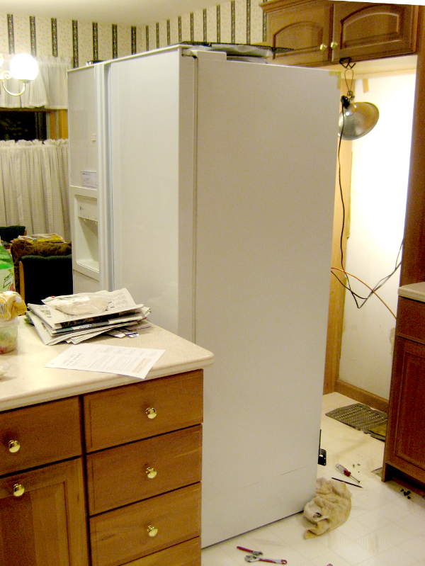
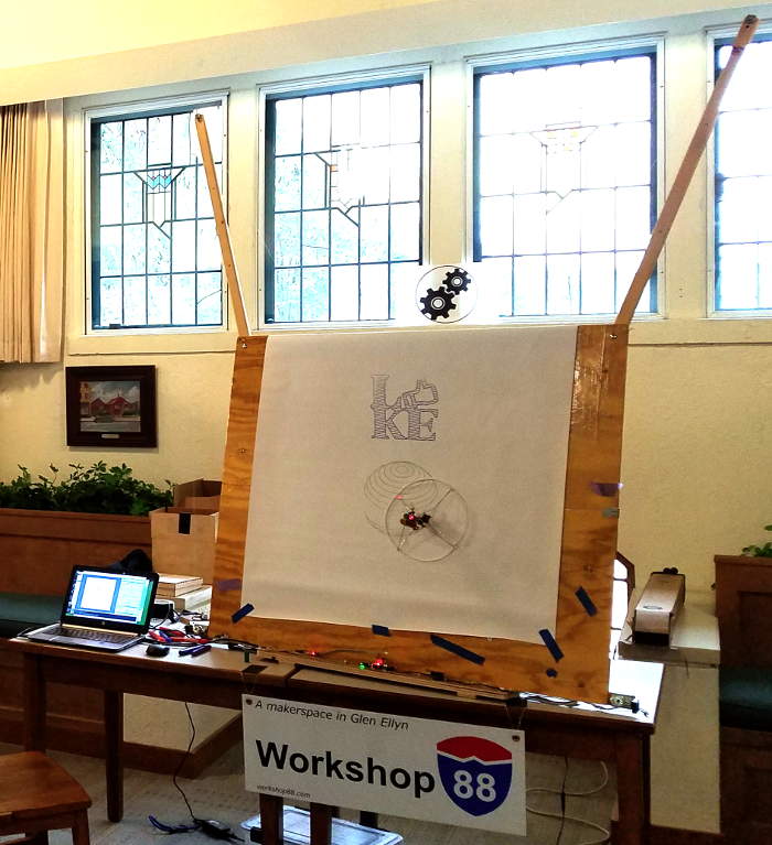
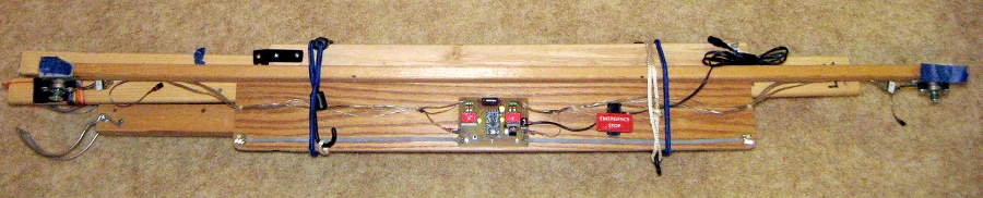
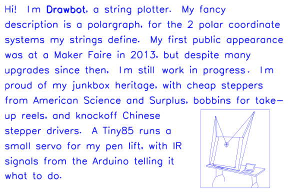
It currently consists of a 4’x4′ drawing area, usually hosting a 40″ tall canvas from a 36″ wide roll of paper mounted on the back. The guts – electronics and the stepper motors and of course lots of LEDs – are all on a long wooden platform across the bottom of the machine. The aluminum pen holder, suspended by two strings going over pulleys at the tops of the “ears” down to drums on the steppers, typically holds an inexpensive felt-tip marker and has a pen lift servo that lets it draw disconnected lines.
Here are some details of its life.
The junkbox spirit
Besides the fun of making it work, part of the motivation was that maybe the appearance of being made from simple, familiar pieces might inspire some kid to say “Hey, I could make something like that!”. That drove many early design decisions.
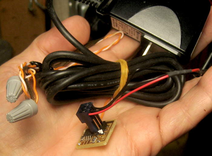
With some real regret, we’ve lost many of those simple parts in a push to make it work better. The Arduino Duemilanove with jumper wires coming out has been replaced by a 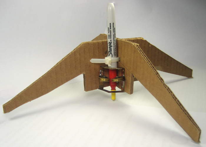
 dedicated Pro Mini on a slick custom PCB with the stepsticks and other parts on-board instead of parts hot-melt glued to the base board. The original cardboard pen holder has finally given way to the nice aluminum and teflon one. And a final death knell will be replacing the cheap steppers and their often recognized sewing bobbin drums with Nema 17s and probably turned aluminum drums. But at least it keeps running better and better. <sigh>
Counterpoint: It’s been pointed out that things that I – as an engineer – see as simple/approachable – like the cheap steppers from American Science and Surplus vs “real” steppers – are invisible to the kids I’m hoping to inspire. And further, that I’m turning a blind eye to other critical parts: Even back when it had a kid-recognizable Arduino, there was so much high powered software hacking behind it that the kid wouldn’t have a prayer of making it work by himself. Yes, inspiring kids is a great and worthwhile goal, but I’m deluding myself about what parts are important to that goal.
Another colleague suggested that familiar things are important in perceived approachability. The bobbins – which I only used because they happened to be a press fit over the gears on the steppers – probably accidentally carried a lot of weight in this area. Yeah, the old cardboard-and-ziptie penholder was probably valuable this way, but I dumped that in the name of better performance, too.
I guess the bottom line in these arguments is that if I want to make something to elicit the “I could make something like that!” reaction, I need to design for that from the beginning, and not delude myself into thinking that some high powered toy that appealed to me will evoke that reaction in a kid. Evoke a “Wow, that’s cool!”, sure – but not “I could make that!”.
Showings
– It was first shown at the Northside Mini Maker Faire in May, 2013.
– It probably went to the American Library Association later in 2013.
– It went to the Mokena Mini Maker Faire 8/22/15.
– Bill took it to a STEM event at Edison Middle School in Wheaton on 1/28/16. It had an early pen lift mechanism, but it didn’t work at the show.
 – I took it to StemCon at COD 4/30/16, with the pen lift working, and where it gained its first roll paper holder. (Dumb: Now it’s up high and pulls down over the top.)
– In considerably enhanced form, I took it to the Palatine Mini Maker Faire at Quest Academy on 5/21/16.
– It went to the Chicago Northside Mini Maker Faire 5/17 with new motherboard and IR comms to the pen lift. It performed poorly, significantly for not understanding new (7.10) software/firmware.
– It went to the River Forest Public Library Maker-Fest 10/7/17 with its new aluminum and teflon pen holder, modified Arduino firmware, epoxied bobbins, and freshly lubed steppers. Worked very well.
Steppers
Having the guts mounted together at the bottom was with an eye toward making a portable device that could (with some stick-on pulleys) draw on whiteboards. Has never happened (yet).
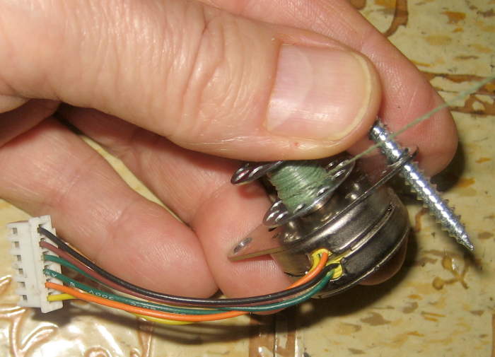 The steppers – the original junkbox parts – were $2.75 at American Science and Surplus. Way too wimpy for what we needed, they got an effective 2X torque boost early on by running a “2 part line” of string over pulleys on the pen holder. A real nuisance to set up, that arrangement was dumped when we started running the 6V steppers from 30V and chopper drivers.
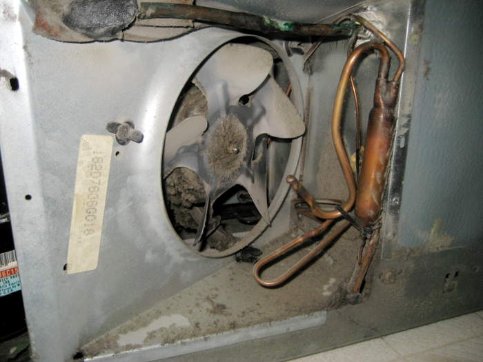
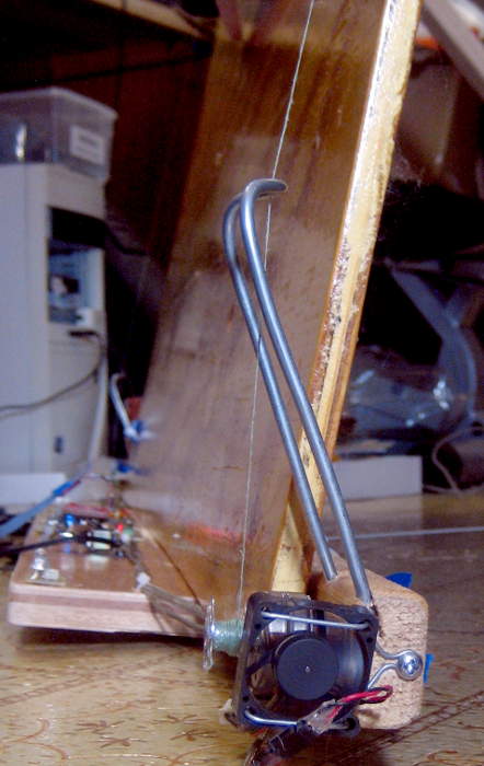
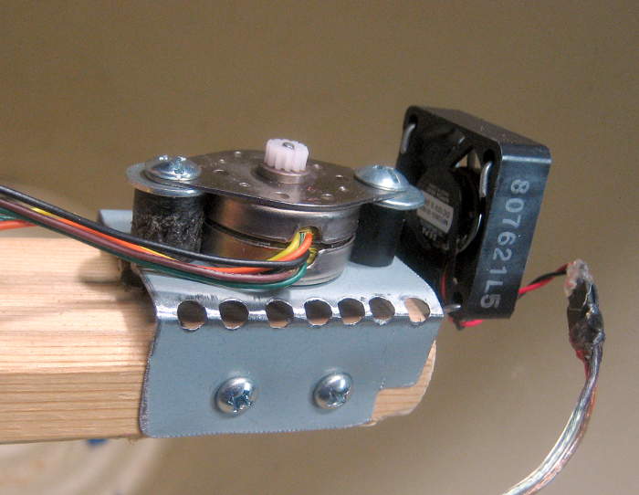
 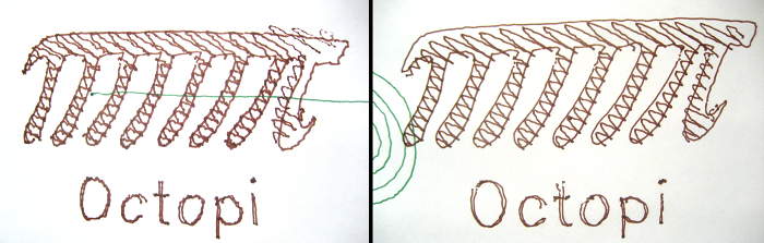 We kept the steppers from melting by adding a dedicated fan to each one.
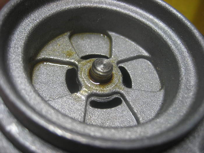
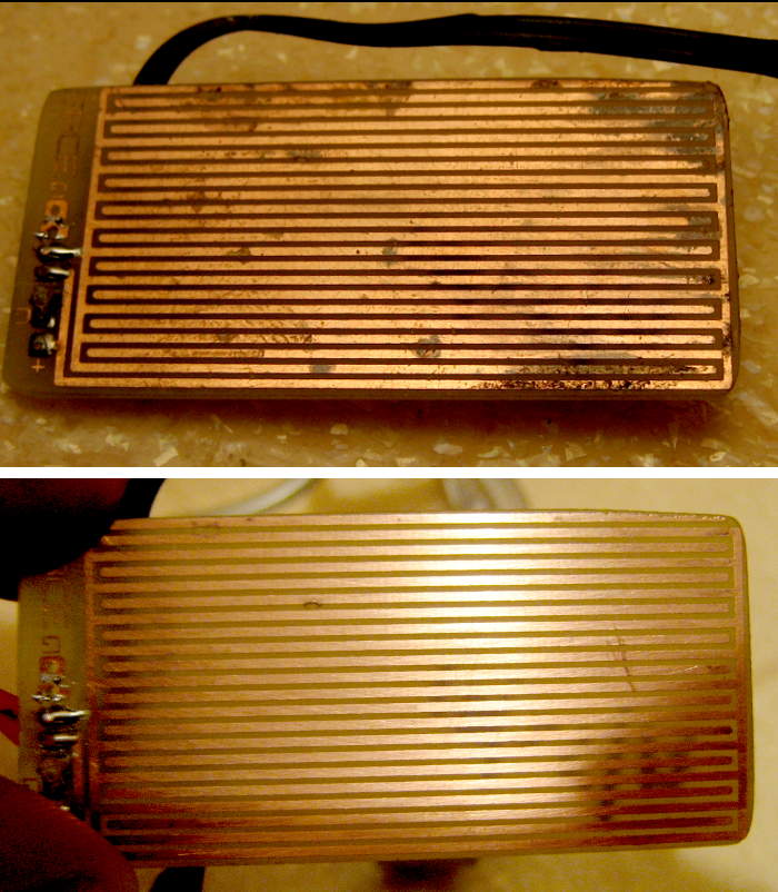
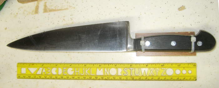
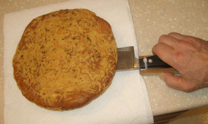
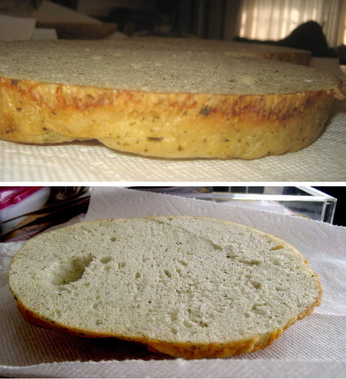
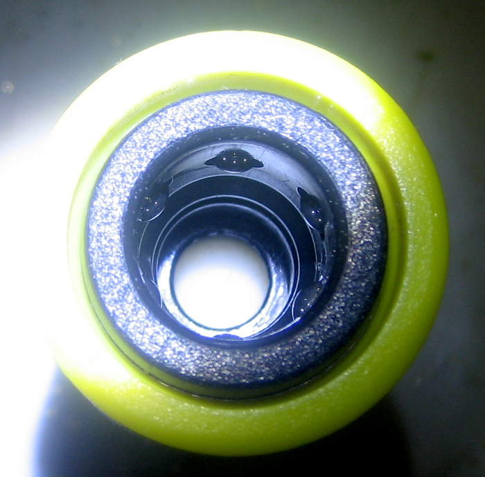
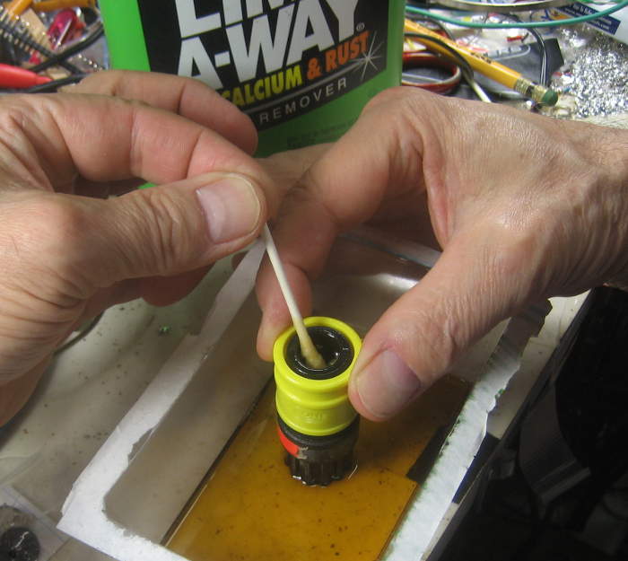
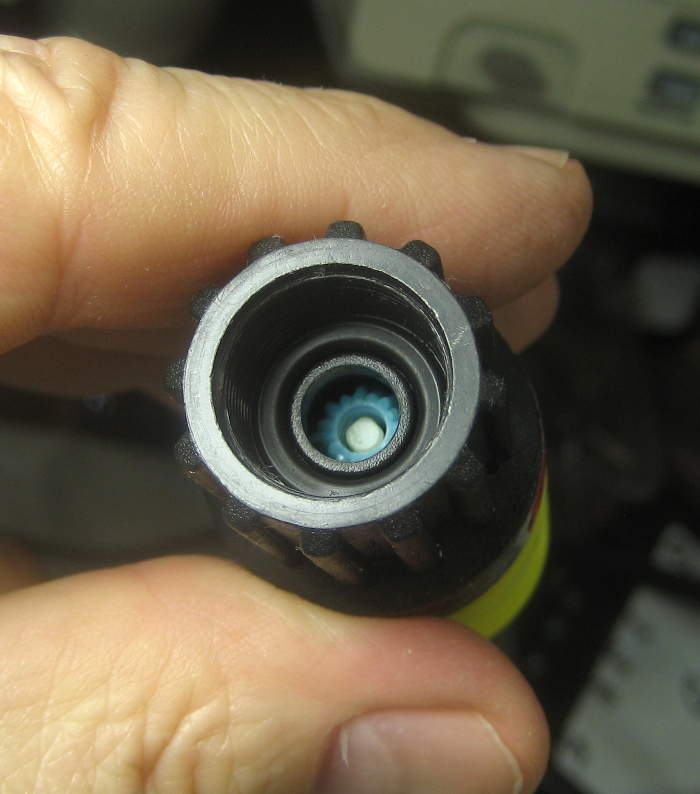
Lubricating them every time we used it turned out to be essential to success. Here’s in indication of the difference it makes:
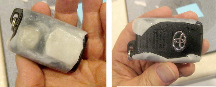
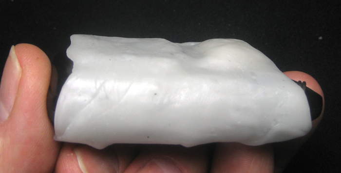
Pen holder
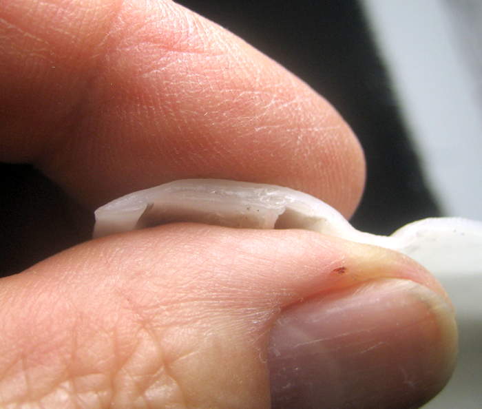
 A pen being dragged around by two strings requires some structure to keep it perpendicular to the paper. The original, with 4 baling wire legs gave way early to a nicely made double-layer corrugated cardboard X, with little bits of teflon glued at the “feet”. That kept the
  junkbox spirit, and worked pretty well for years. After while it got upgraded with the first pen lift servo. But its little feet got caught on the edges of the paper, and it eventually got pretty beat up.
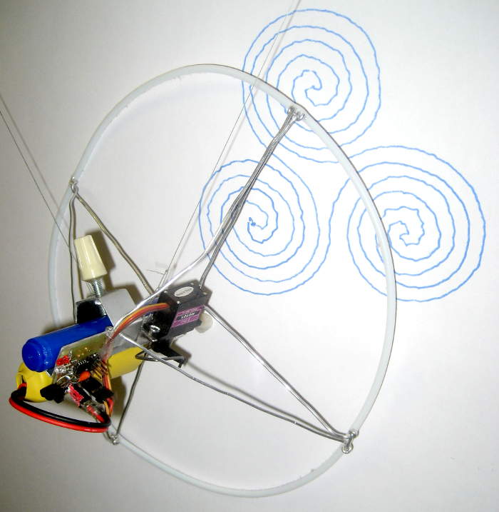
The main driver for the new pen holder was that by having a ring touching the paper (instead of 4 discrete feet) it could go past the edge of the paper and come back with nearly no chance of getting caught. I hoped it would be a little lighter, too, though I failed to weigh the old one before raiding its parts, so I don’t really know. 🙁
 The 3D printing revolution came to help here: I got a meter of 2mm ID teflon tubing for $2 on eBay – perfect for the ring! It was of course for a Bowden extruder for 1.75mm filament. Getting the aluminum wires that went thru the tube connected to the wires that held it to the pen holder’s aluminum angle backbone took some clever engineering, but it came out fine.
Practical stuff
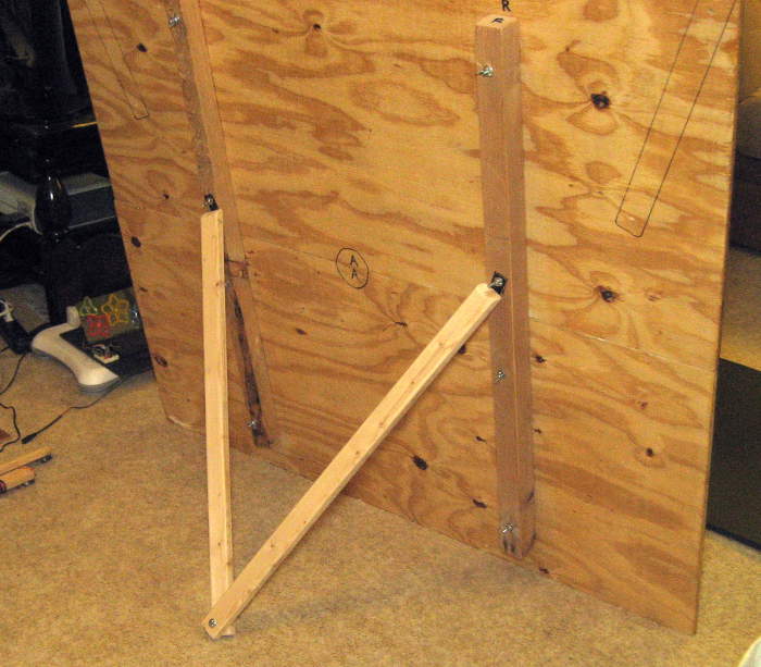
 Of course the machine is too big to put in my car to haul to events, so it has to come apart and go back together simply and quickly. Some of making that happen was thoughtful design, some just practical packaging.
A Workshop 88 sign hung from the 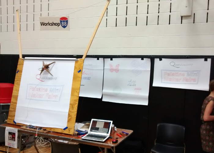 “ears” at one show. Meh.
The ears position the top pulleys – where the string comes from – much higher and farther outboard than the upper corners of the backboard. “Higher” is needed for the problem that when the pen goes up high and the string angles decrease, the tension in the strings – and thus the torque needed by the steppers – goes way up. With no torque to spare, we sidestep the problem by never needing those angles – even with the pen at the top of the paper. “Wider” helps drawing at the edges of the paper, where with one string almost vertical, we lose the needed horizontal component to move the pen.  By having the strings much wider than the backboard, we can draw very near the edges.
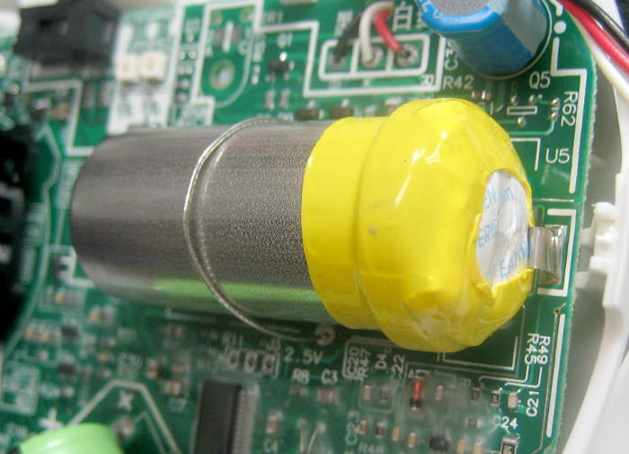
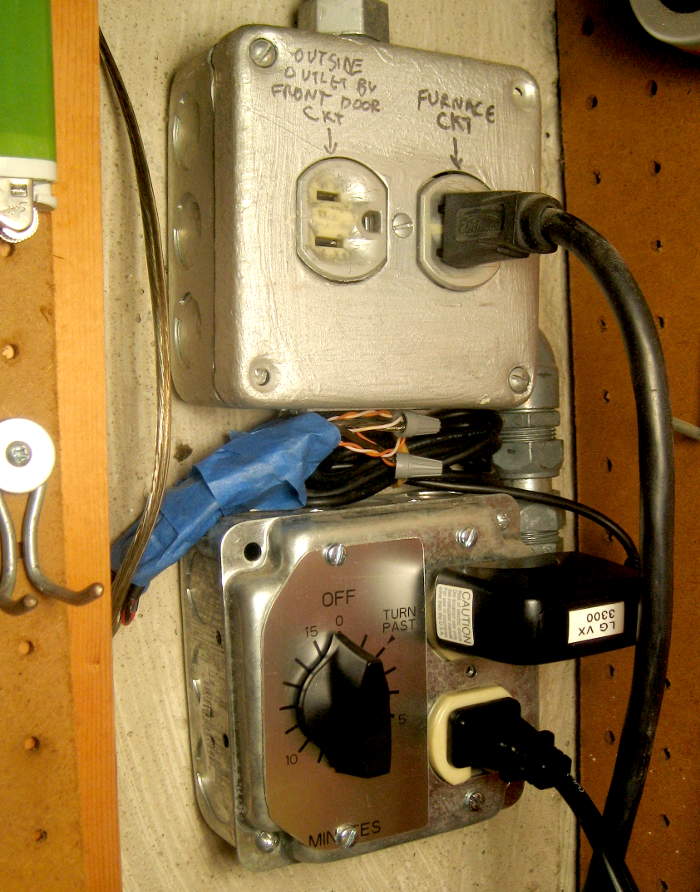
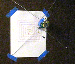
For the math to work right, it’s critical to know where 0,0 is. An LED (powered with a 2032 coin cell) stuck part way thru a hole drilled just at the origin glows thru each new piece of paper to get restarted quickly.
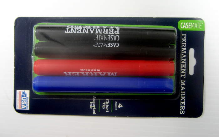
 While I stock up on cheap markers at Walmart before each show, it’s still helpful to stretch the life of each one. Ten drops of alcohol works well to get one more life from a marker.
As the string winds up on the bobbin drums, their diameter changes in a way the math doesn’t expect. Drawings get pointier out toward the top corners as the drums wind more string and get larger. Getting rid of the “2 part line” pulleys cut the amount of 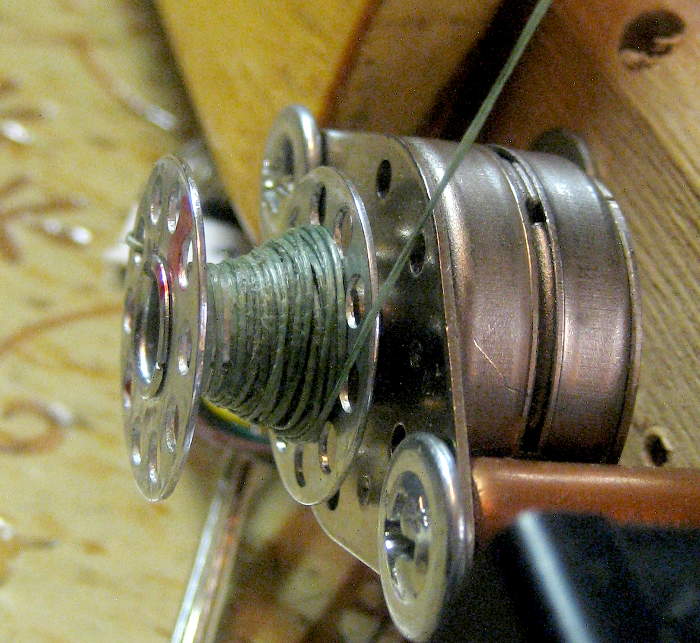 string – and the diameter error – in half, which helped considerably.
 But if the string winds unevenly – piling up at one edge – the problem becomes even more severe. To wind uniformly on the drum, the string must come in very accurately perpendicular to the axis of the drum.
 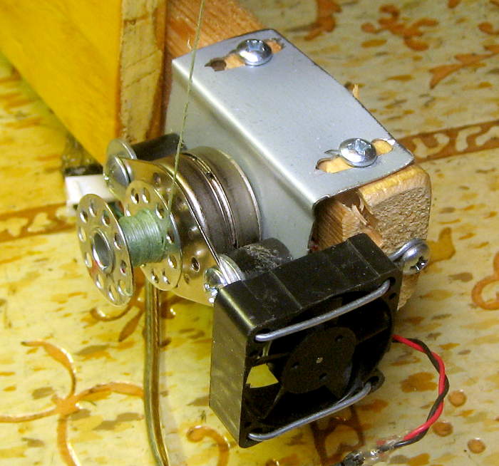 An early attempt to address this used big stiff wire guides to manage the string. The later approach was to create adjustable mounts for the steppers. That worked pretty well.
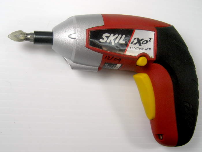 Winding all that string back up on the bobbins after a show is a pain. I used a small electric screwdriver with a Philips bit covered in hot melt stuck into the bobbin hole at one showing – worked well. The current version has a button at each end of the main board that just tells the Arduino to wind the string in. Very nice.
 As for the string itself, the most critical characteristic – especially with the long runs the drawbot has – is that it doesn’t stretch. Braided fishing line is optimized for just this property, and it’s cheap and plentiful. One down!
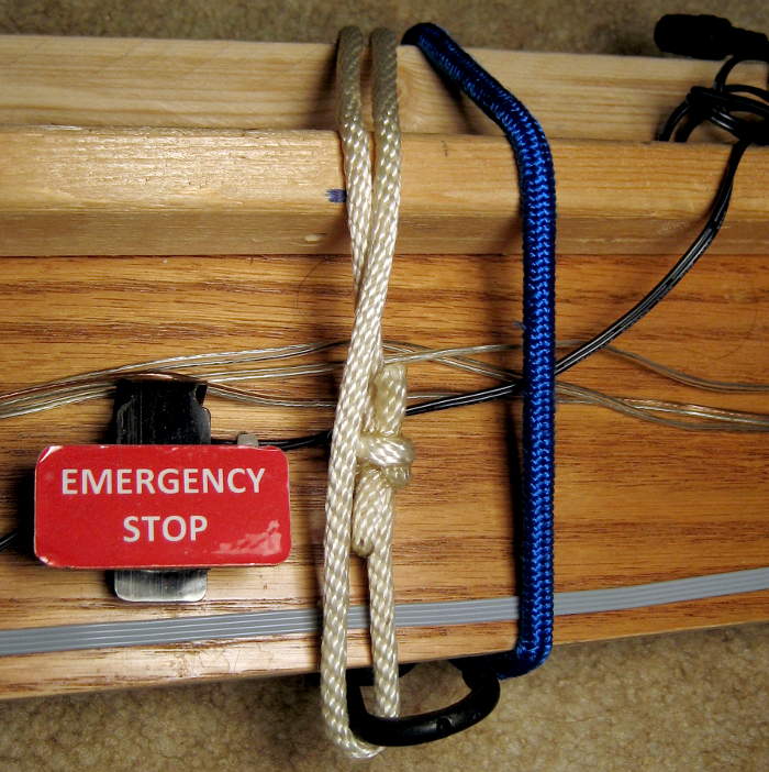
 There’s a bunch of “long stuff” – electronics/stepper board, ears, back braces, rear prop – when the drawbot’s torn down. Keeping it together – either for transport or storage – is a fine job for bungee cords. Unfortunately one cord didn’t work, and 2 cords was awkward overkill. I finally got around to making some loops of 1/4″ poly rope that fit just right with one cord. Small stuff, but it pays of with every setup/teardown cycle.
Electronics
An Arduino accepts ordinary gcode over a serial link, does the math to convert from X,Y coordinates to the L1,L2 length-of-string coordinates needed by the drawbot, plans the paths, and runs the steppers. It also uses its EEPROM to store some config info.
 When it first started drawing, the drawbot used a pair of Chinese L293D H-bridge modules borrowed from another project to drive the steppers. Later, its custom PCB hosted (knockoffs of) Pololu’s classic A4988 microstepping drivers. (An error in the Reprap Eagle library I used caused a lot of excitement when the drivers had to be installed upside down! Some more in the Gory Details.)
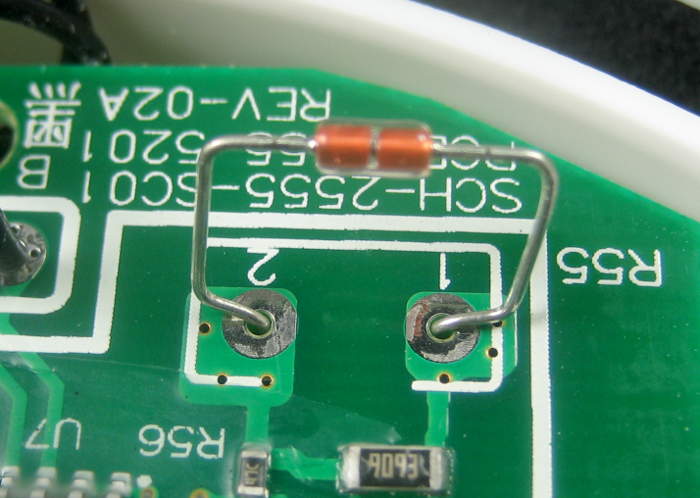
To let the steppers cool down a little while still holding the penholder up, a simple circuit with a big 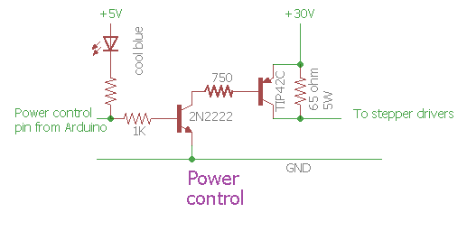 resistor and a power transistor cuts the voltage when it’s not actively drawing.
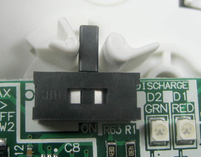
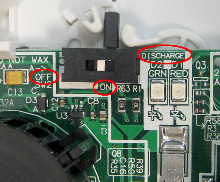
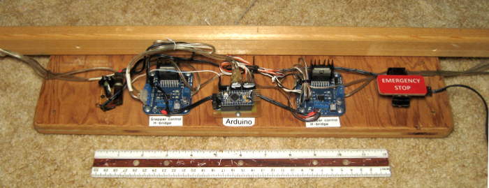
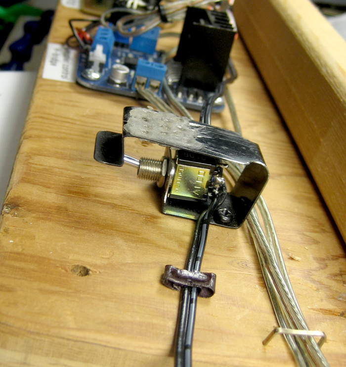 At some point shortly after watching in horror as some error caused the penholder to sail gracefully up over the top of the board and fall down behind it, it gained an Emergency Stop switch in series with the power supply. It gets used a lot in testing and debugging new artwork, as well as being a general power switch for the steppers.
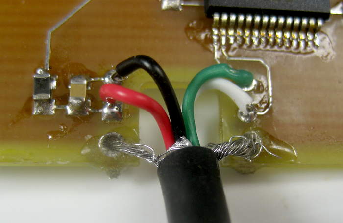
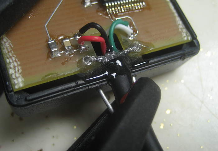
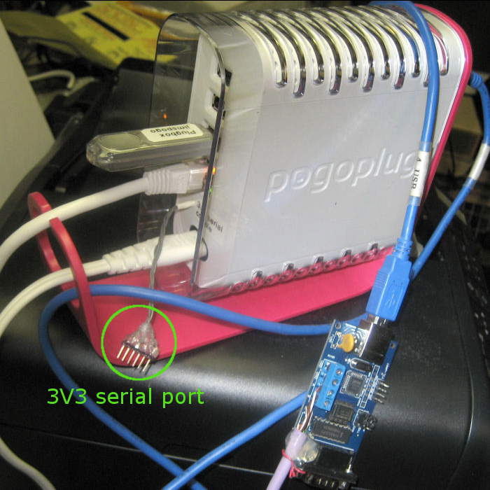
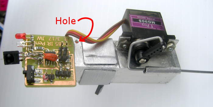
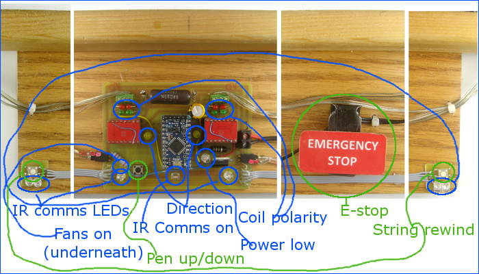 The latest version also has 6 IR LEDs spread across the base and shining up to send pen up|down signals to the pen lift processor and servo on the penholder. Optimizing that IR communication took me deep down a rabbit hole, written up here. Sorry for the messy picture. I should redo that. 🙁
And lots of LEDs! Most every function – current polarity for each coil of each stepper, direction of each stepper, voltage reduction state, IR comms, fan current monitoring, even pen lift state on the penholder itself – has LEDs. Of course they add great bling, but are also quite helpful in troubleshooting when things go wrong.
Software
Dan Royer, at marginallyclever.com sells kits for drawbots, and has graciously made his code also available to others making their own drawbots. The Arduino in ours has run various versions of his code since day one, and the laptop sending gcode to it has run Dan’s Makelangelo Java gcode senders as well. Thanks, Dan!
Of course our hardware is different from Dan’s, so we’ve had to modify each version of his Arduino code to support our stepper drivers, power control, pen lift and other hacks. And his code only supports straight lines (no G2/G3 arcs?!), so I had to add those in, as well as adding support for G55-59 alternate coordinate sets so I could put multiple drawings where I chose on the big paper. I learned a lot about gcode interpretation in the process. 🙂
Next steps
Taking a final step away from junkbox, I’m planning on replacing the dear old Science Center steppers with “real” Nema 17 mount motors. Their increased torque and finer step resolution should let me use much larger diameter drums (sadly losing the friendly sewing machine bobbins). That should further reduce the “pointy top corner” problem, and maybe allow for shorter ears (lower, though just as wide). I’m hoping it will also help with occasional missed steps I see now.
The real solution for missed steps in any CNC machine is for the gcode reader/planner to incorporate acceleration control. Unfortunately, Dan’s code doesn’t provide this. Fortunately, another common Arduino gcode/stepper driver, grbl, does. And even more fortunately, someone has already put the inverse kinematics math for string plotters into a version of grbl!
And while grbl also supports G2/G3 arcs and G55-59 alternate coordinates, I’ll probably have to hack in support for my steppers, and certainly for my power control, pen lift and rewind buttons. That should be doable. Of course Dan’s gcode sender won’t talk to grbl, but the Universal Gcode Sender we already use on the Shapeoko does.
It should all be workable, but it will take another bunch of time to get it all implemented.
[And I suppose instead of just hoping the “real” steppers will magically improve things, I should do the testing on the current hod-rodded steppers so I know what their torque is to make choosing the next stepper a little more scientific. Ugh.] Done. See here.
TL;DR gory details
I’ve pasted in some notes made along the way, many not cleaned up. Also notes to myself about things to cover. There’ s still a lot of work to finish these sections up. Work in progress.
Pen holder
Work started in earnest by deciding whether to use 1/2″ or 3/4″ aluminum angle to hold 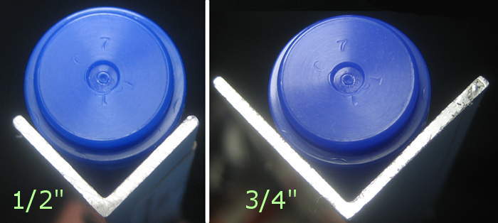 the pen. The 1/2″ clearly was big enough to touch the nice cheap Walmart markers I’ve settled on at the right place, but I went with the larger angle mostly to provide comfortable margin for holes to attach the strings and to give more surface area for gluing other parts on. (Sigh – I had really hoped to aluminum braze the parts together, but I seem to be too reluctant to try it. I have aluminum rod (from HF) and a new stainless steel brush bought just for the purpose. It’s occurred to me while reading up on it that maybe you could “tin” the parts with the rod and then just sweat them together without worrying about the oxide layer. But I’ll never know ’til I try, and I seem to be afraid to try. 🙁 )
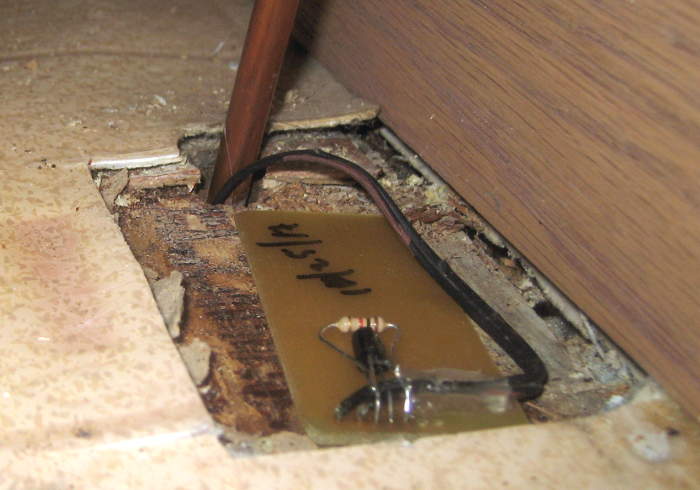
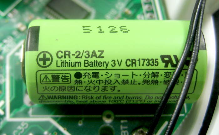
 Then came the sad task of disassembling the dear old cardboard and brass holder. The IR receiver, pen lift servo and Li-ion cell will be reused on the new holder. I apologized to the old holder with each removed part, reminding it that it had drawn a lot of really great pictures.
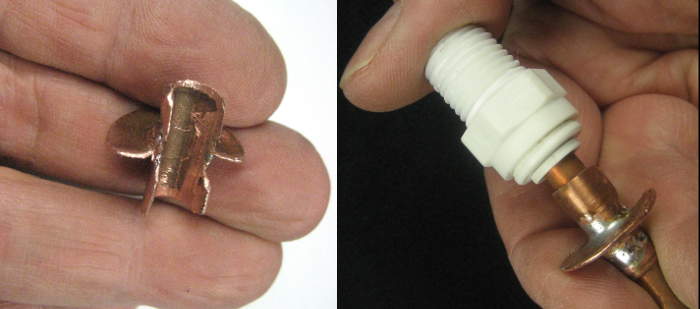
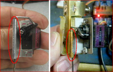
 The very nice penlift servo used a brass tube soldered to the brass penholder angle. That’s obviously not a good solution for the new one. I replaced the otherwise perfectly usable aluminum bracket the servo was mounted with with one larger in the dimension toward the tube, and rolled the end of the bracket into the tube. To do that, I crimped the aluminum tightly around a nail slightly larger than the sliding rod, then
  drove the nail out. I suppose I could have just glued another piece of aluminum under the bracket and make the tube out of that, but I seem to have done a fair amount of extra work just to make it less ugly.
The old bracket was epoxied on. I pried/cracked it off, gaining a data point on how well it held. (Pretty well, and certainly well enough.) I got a similar data point prying the IR receiver PCB off its aluminum bracket. (Also quite good enough; all epoxy stuck to the  PCB, not the aluminum.) I removed the penlift’s Shapelock foot with hot water. It was way bigger than it needed to be, and had to come off anyway to remove/reuse the coathanger linkage rod.
While I’d long envisioned pairs of stiff wires attaching each of 4 or 6 points on the teflon ring to the top and bottom of the central structure (forming nice triangles), I realized I didn’t actually have a plan for how the wires would attach. The aluminum angle that is both the main part of what grips the pen and the backbone of the whole structure is fairly busy and obscured by various parts, and it looked like it might be more awkward than originally imagined. Time  for a physical prototype to look at and turn around and poke at. Some 18 ga baling wire unrolled and a scrap of angle with parts taped/glued on showed me most of what I needed to know. Completely non-working, throwaway prototypes can be so useful!
While I’d long envisioned bits of the wire in the teflon ring being exposed for connection to the support wires, I had no idea how to actually accomplish that. A critical requirement is a continuous, smooth bottom on the ring (OK, an exception is where it joins itself). That means the exposed wires will have to peek out of an opening in the top of the tube.  A couple of practice runs on scrap helped a lot. An unexpected lesson: use needlenose pliers with SMOOTH jaws! That soft aluminum wire mars really easily, but its ductility is a boon to making those exposed loops! I may have to figure out how to un-mar the wire to make it less ugly. So much for function over form.
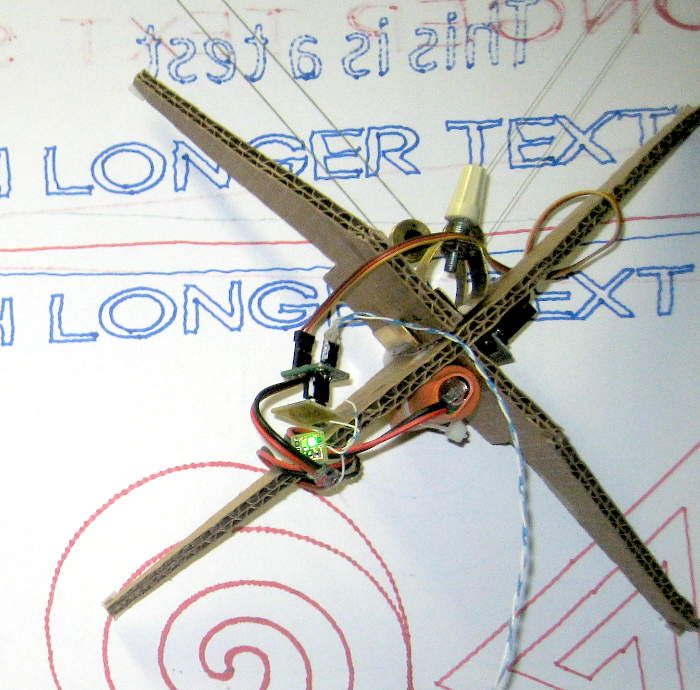
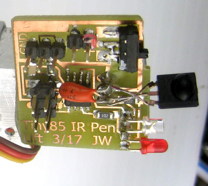 One issue holding the parts together to look at revealed was that the lens of the IR sensor was pointing about 180 degrees from where it needed to look. I ended up just twisting it. Despite appearances, those carefully hand-formed leads do not touch.
Since I chickened out of brazing the aluminum parts together, I used the fallback of (HF 5 minute) epoxy. Spooked by bits I’d read about bonding aluminum with epoxy, I tried to do very good surface prep. I even wet sanded with epoxy for the servo.
I had a lot of trouble with epoxying the nut in place for the pen clamp. Of course I sanded the Al with 80 grit or so, and then scratched the epoxy in with the tip of a screwdriver (sanding was difficult). Unfortunately, the prep took too long, and the epoxy was way too far along when I assembled it. Trying to build up fillets with the remainder of epoxy was near impossible. I clamped the nut in place with jam nuts on the screw from the old clamp. It seemed OK, but when I twisted the aluminum to set up for attaching it to the main angle, I heard the epoxy crack and the nut came off fairly easily. Second try I wet sanded the epoxy in (Qtip wrapped in sandpaper). I mixed up a little additional batch of epoxy and enhanced the fillets, and again clamped with the target screw. Unfortunately, some epoxy must have gotten into the threads, and when I used a wrench on the jam nuts to get it apart, the nut broke loose. I’m guessing that if I’d oiled the threads beforehand it would have been fine. Given the torque I applied with the wrench before the nut broke loose, it seemed well bonded.
 For the third try, I wet sanded some epoxy onto the Al and wiped it off with a paper towel. It was already fairly stiff. The goal was to leave a thin layer of epoxy that had been sanded in to seal the Al. Without giving that batch any more curing time, I mixed another batch and used that to glue the nut on. I clamped as before – but with oiled threads! Finally I built up nice fillets while the epoxy was still OK. The screw came out of that with difficulty
 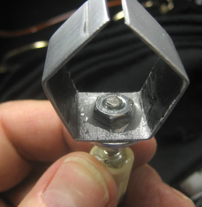 as well, but now I was clever enough to hold the *nut* instead of the bracket so as not to stress the glue while trying to get the screw out. After picking bits of epoxy out of the nut’s threads with a pin, the screw moved pretty freely. I think the nut is at least well enough adhered for the task.
TEFLON RING
Using the “I dunno – that looks about right” design approach, I decided the ring should be about 9″ diameter. I cut the tubing for that 28 1/4″ circumference.
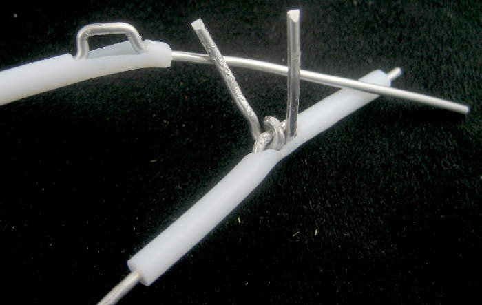
The wire needed that length, plus a little for the connection loops peeking out of the holes on the top of the ring, plus enough for all the runs attaching its connection loops to the pen lift angle backbone. It would be more elegant if the wire were all one piece – but how to route it? 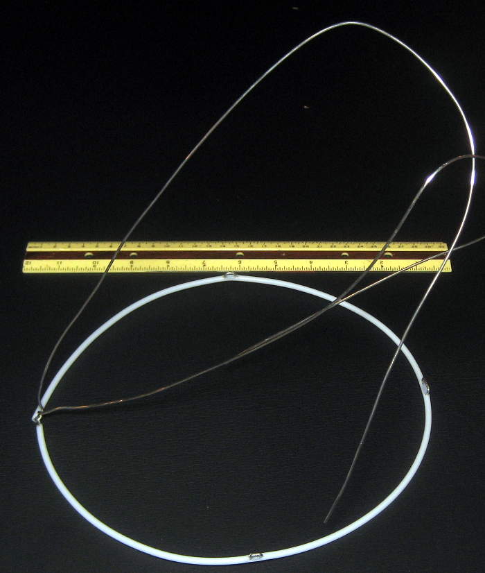 The baling wire proto above and a surprising amount of mental arm waving and sketches yielded a plan, and the fact that the 2 sets of holes on the backbone angle are 2 3/8″ apart let me compute the wire length for the 8 connecting segments. Here’s the wire, cut to length (plus a little!) and threaded thru the tubing, with the connection loops formed.
 The minimalist aluminum backbone angle really only has room for holes for the strings in one place, so I drilled them there. I hope I can move the Li-ion cell enough to make that also be the balance point! Update: Yes I could. Balance is just as planned.
RING-BACKBONE CONNECTION DESIGN REALIZATION
With 8 stiff wires connecting the backbone and ring, it’s wildly over-constrained. That means the wires have to be exactly the right lengths. I can easily see a crooked backbone or other problem. The distance of the ring above the paper when plotting is pretty critical, and there’s not much room for adjustment after it’s all wired in place.
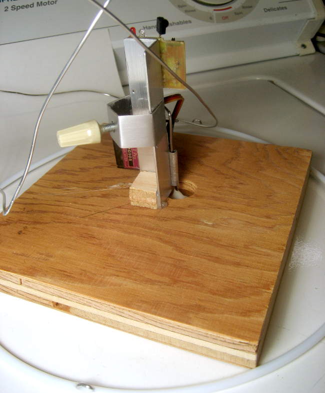 To address some of that, I attached the backbone rigidly to a jig/platform that keeps it at least: a) vertical (/perpendicular to the plane of the ring); b) roughly centered, if only visually; c) the right distance “above” the ring. With the stop I hope to provide for defining the pen position (hmm – I guess that’s really the midpoint of the penlift travel), the bottom edge of the backbone should be just 3/4″ above the paper, so I made the support platform that thick. Of course I had to drill a hole for the pen lift foot. Pen foot travel puts it min 0.5″ and max 1″ below the bottom edge of the backbone. Measured outside diam of ring is 9.25″, ID just about 9″. I cut a piece of 3/4″ scrap to just fit inside that, marked it and drilled a hole for the pen lift foot. I glued a square block to the base, and the backbone to the block (all hot melt, as this jig will have to come apart again soon).
Well, rats. The top holes in the backbone are fine, but for the bottom holes, barely above the surface of the platform, the straight lines from them the wire must take to the attachment points on the ring go almost completely thru the wood! Maybe I can cut grooves for the wires in the wood without cutting it completely apart.
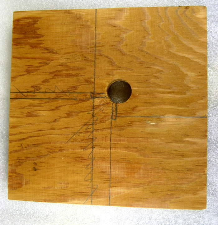
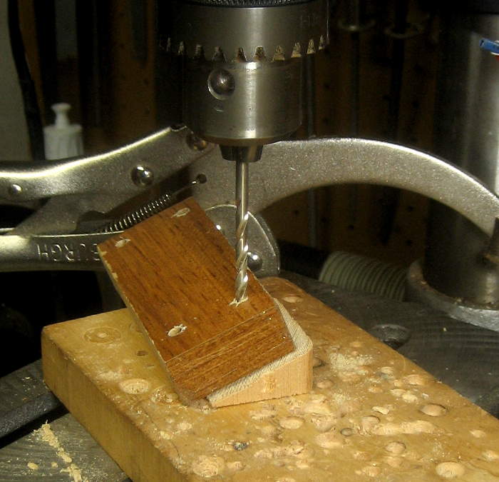
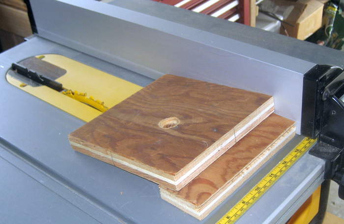 OK, here’s the outline of the angle and the centerlines of the paths the wires need to take. Yeah, yeah, the scribbled out ones are wrong. And here’s the setup to cut the needed angled grooves. Fortunately, one saw kerf is just nice clearance for the wires.
 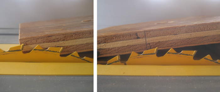 But to provide clearance for wires going thru the holes, the block that holds the backbone had to be moderately cut away. Here’s the new
 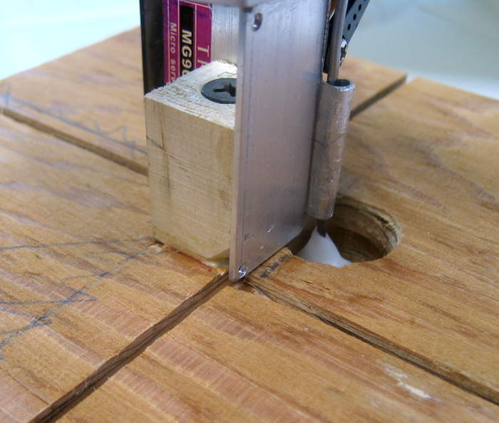 one, taller and screwed (and wood glued) to the platform. Wire bending time!
Well, rats. I didn’t think it thru well enough, and there’s no way to route the wires as I’d planned without going diagonally thru the pen (not a good thing). OK, what if I recut the grooves so this one goes this way and that one… nope. My head was fully engaged in having one piece of wire, but there’s really no reason it has to be that way. And if I make it 3 pieces of wire, 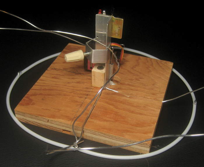 I can route them so they don’t interfere with anything. But it was supposed to be one piece! Shut up and make it. It took hitting the chocolate for solace and courage, but I got started bending.
The platform/jig holding the backbone was a big help keeping things centered and square as I ran the wires. When all the wires were in place (though without final crimping) I took it off the jig to finish up. Unfortunately, I’d taken an easy way and ran the wires with just a 90 deg bend thru the holes rather than the 270 I’d planned. After it was off the jig, I realized it would be a lot sturdier the other way, and redid 3 of the 4 holes. (I’d already crimped and cut one of the original ends of the single wire, so didn’t have enough to redo that one.) Lots more adjusting and finessing, and I got it so the ring was pretty flat on the 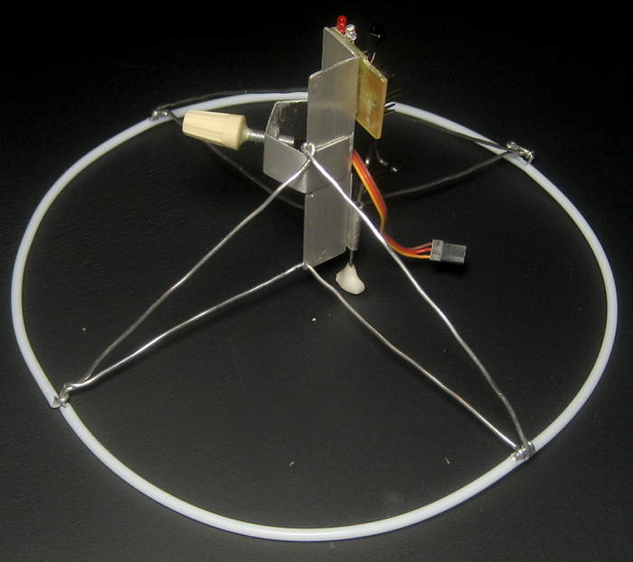 ground with the pen lift at the center of its travel, and crimped and trimmed all the ends. The wires are moderately nicked up and ugly, and the pen is considerably farther from center than planned (how did that happen?), but it’s fully functional. Another step done!
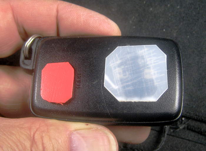
Pen lift
 The wires dangling from the pen holder in early 2016 to control the penlift had to go. Bill proposed using RF; I proposed IR. In a whole nother effort, I looked at increasing the range of the IR LEDs by increasing the current pulses thru them while decreasing the duty cycle (to avoid melting them). That bit of unnecessary over-engineering got its own whole writeup.
The pen lift is triggered by hooks in Dan’s code that look at any Z value above some threshold as “pen up”, etc. I hacked in a function to send the IR pulses to say “pen up” or “pen down” in a simple custom protocol, and called that from his Z value tests. There’s also a button on the main board to toggle it manually. That’s good if it gets into the wrong state (almost never happens) or to drop the pen for a moment to make a dot on the paper in case I need to find local 0,0 again for a drawing – like for switching pen colors if it’s missed a few steps. Or to demo the pen lift. 🙂
NEW PEN LIFT LINKAGE
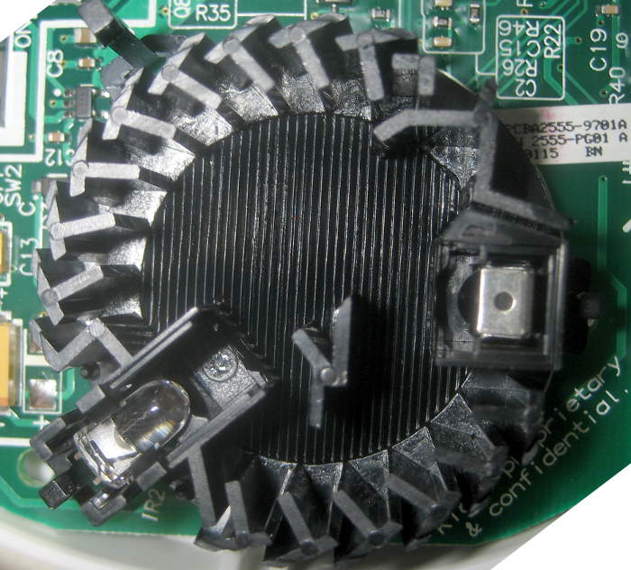
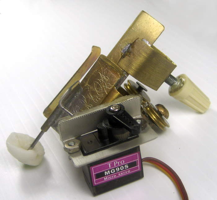
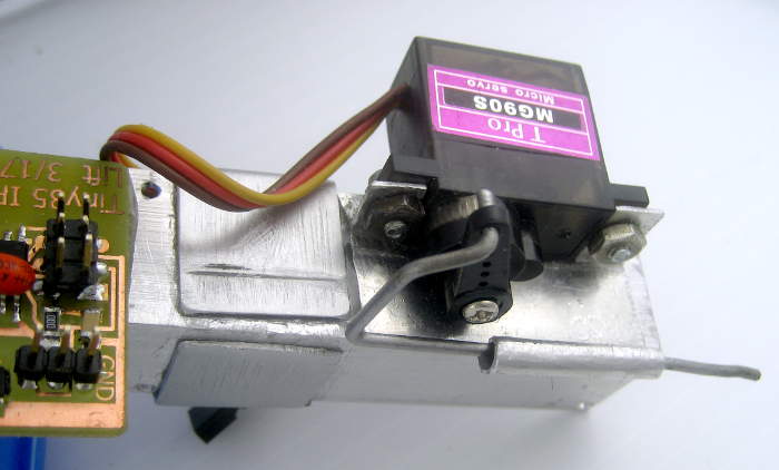
The drawbot had gotten the mechanics of a pen lift – a servo on the penholder controlled by a local Tiny85 – in January 2016. Here’s a clip of that penlift linkage. Rather than lifting just the pen off the paper, it lifts the whole penholder up by pushing a foot encased in slippery Shapelock against the paper. The original Shapelock foot was way bigger than needed; a much smaller one graces the new aluminum penholder.
 At some point, it hit me that the aluminum tube I’d rolled for the linkage rod was way too long, and would never allow enough travel for the pen lift. It was easy enough to cut it down, but embarrassing that I missed it to begin with.
 While I got the old penlift linkage rod to work well with its new aluminum guide tube, there was a problem: The way it’s mounted (the servo and especially the foot are below the pen), that rod is trying to fall out of the hole in the servo horn. The fit is pretty free, and I’m quite afraid it will fall out in use. So how do I keep it in?
If it were 5 times bigger, I’d drill a hole and use a cotter pin and washer. Ideal would be a push nut, but I doubt I could find one just the right size. I can’t heat it, as it’s millimeters away from the plastic horn. I could carefully file a groove around it quite near the end. That opens a couple of possibilities: I could put a very small blob of epoxy on the end, relying on the groove to help it stay there. A small washer would be what touches the horn. Or I could try to make a circlip to fit it. (I seem to think that more feasible than making a push nut, but still a big hassle.) Or I could make a ring of wire to be held in place by the groove but extend well beyond the rod’s surface. The bit where it was twisted to itself would also help hold the rod in. In fact, by twisting 2 bits of wire together with their twisty ends diametrically opposite, there would be pretty nice symmetrical wings to bear on a washer between them and the horn. None of those resonated with me.
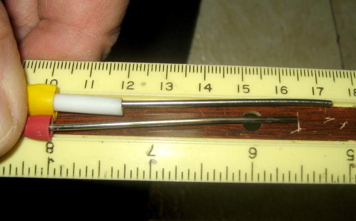
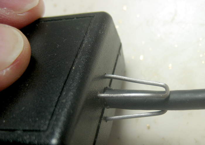
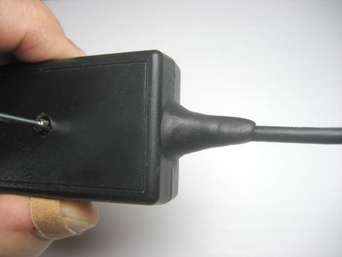
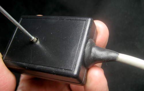
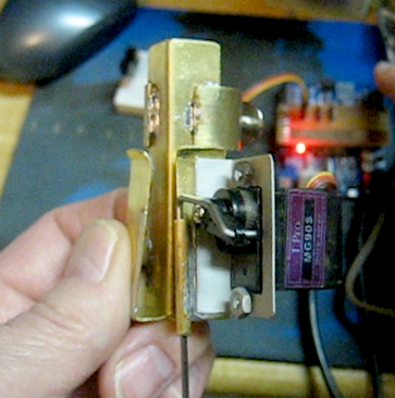
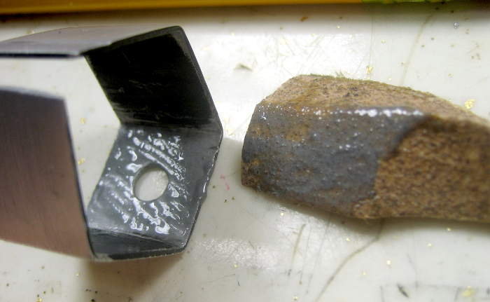
But in fantasy walking thru a discussion asking for ideas on Slack, somebody might say “If it tries to fall out, how about making it come in from the other side so gravity helps rather than making it fall out?” Well, gee, if I made a new one and bent it a little differently, that would work! After finding and polishing up another piece of the 0.060″ coat hanger wire the original was made from, I started fitting it, 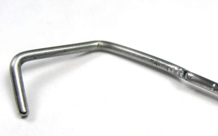 but needed to rebend one bend – twice – and metal fatigue struck. To avoid the same problem again, I made a prototype of 0.046″ baling wire. Much easier to bend, and more forgiving. Here’s the
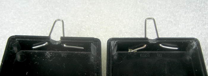
 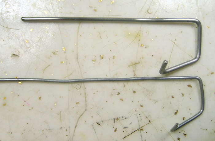 skinny proto and the working rod modeled on it together. The new rod works fine, and can’t fall out. Here’s the old and new rods
 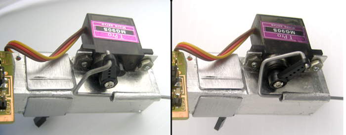 (view from below pen holder when it’s in place). Thanks, virtual W88 consultants!
Paper holder
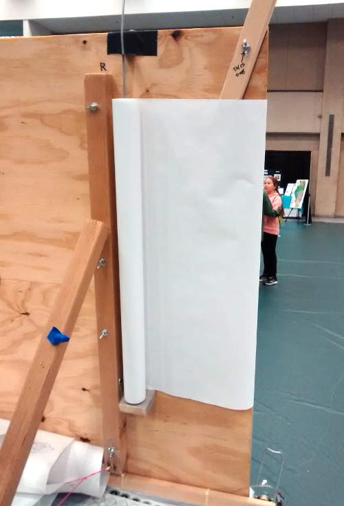
 Trying to cut a new piece of paper for each new drawing from a roll, and fighting with curling to boot was a hassle. At STEMCON in April 2016, I added some bits to hold the roll of paper vertically on the back. Much more convenient, but duh: Why not mount it horizontally, right at the top on the back, so I could just pull a new piece of paper down over the backboard? And if the roll were mounted the right way, going over the top of the board would actually uncurl it! (Hmm – it looks like it might have used narrower – 24″? – paper and actually been pulled around the side, also uncurling it, at that show.)
By the Palatine Maker Faire in May 2016, the simple, effective new holder for 36″ paper was in place. (I’ll get a picture next time it’s together – sorry.) I made up a piece of aluminum angle that clipped over the top of the board as sort of a paper guide and to hold it down, but that wasn’t really needed, and so seldom gets used any more. The paper holder is a great addition, helping turn the drawbot from a curiosity with a piece of paper taped to the front into a production machine for producing sheet after sheet of drawings. All for a couple of pieces of heavy wire and 4 screws. (And struggling thru several shows before it hit me how to do it.)
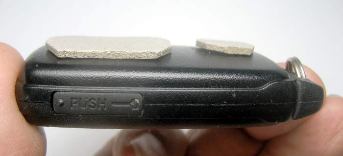
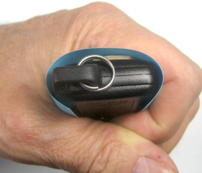
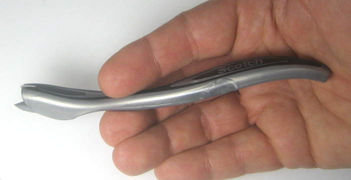 Cutting the paper off at the top when it’s full and ready to be hung up is a lot easier (and more professional-looking) thanks to some little coupon clipper paper slicer with an enclosed blade. And after I figured out that I should take the tape off the bottom corners before I slice it off, it’s even less comical. 🙂
Pulling the paper down under the pen holder is awkward, but by the River Forest MakeFest I’d figured out that I could just park the penholder at 0,700 – dangling in the air above the backboard – out of the way, while changing paper. On low power, the steppers still have enough holding torque to support it, and pulling the paper down is much easier! Another step toward making it a production machine.
Artwork holder
Now that the drawbot’s getting to be a prolific picture maker, hanging its artwork has 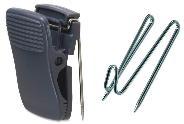 become an important part of displaying it. In case my assigned table is out in the middle of the floor with no wall behind it, I’ve thought about making a large (8’W x 7’H?) frame out of PVC pipe (or 1/2″ conduit?) to hang stuff from. Looks like there are PVC furniture fittings that might be useful. Maybe with lightweight fabric stretched over it to pin stuff to? Maybe use pins like these? Maybe carry the pins always in case of fabric wall? Since pages of drawings are 36″W x ~32″H, size the frame with that in mind. That proposed (big!) 8’x7′ would allow 3 sheets wide by 2 high. The drawbot puts out more that than at a typical show. Maybe cut up sheets and just post the best drawings?
Many fittings would obviously not be glued for quick assembly/teardown. Sensible might be to package up all the parts and leave it in the car to be fetched only if needed. Should be fun to design, though it’s nothing but hot air at the moment.
Arduino software
tried to adjust for drum size changes – failed; interesting adding G2/G3; adding G55 was huge; how hard will hacking grbl be?
Stepper mounts
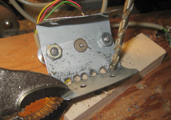 Took off the motors to: drill holes to make “hinges” in the mounting brackets; drill reliefs in the 1×2 for the nuts holding the motors to the mounts for greater travel for axis adjustment; drill a hole for easier application of lube to the back bearing. Holes for “hinge” behavior should have been drilled in the first place – think I just forgot. Small lesson: taking the motor off the bracket was a good idea. I left the first one on “to save time”; not a great choice. Forstner bits would be good for the relief holes. HF has a set for $10. Don’t really want to go just for that.
 OK – drilled relief for mounting bolts, nuts, and oil hole for back bushing. Drilled lots of holes to make a “hinge”. Banged on some of them to correct one bracket that was a bit too tall (for the wide dimension of the 1×2). All back together again. Aligned the bobbin axes for moderately more uniform winding. Calibrated spool diams by drawing line x-300->x300 at Y300 and at Y-300. Got pretty close.
Stepper fans
 When I kicked the voltage up to 30V, I suspected the steppers were going to get hot. Sure enough. But how hot, and how hot is too hot, and how do I prevent that?
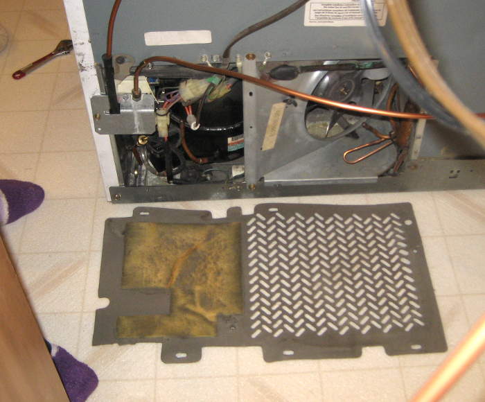
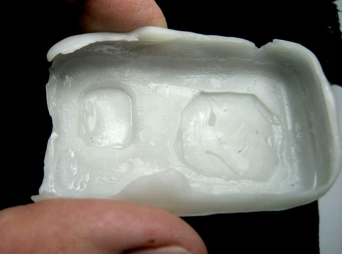
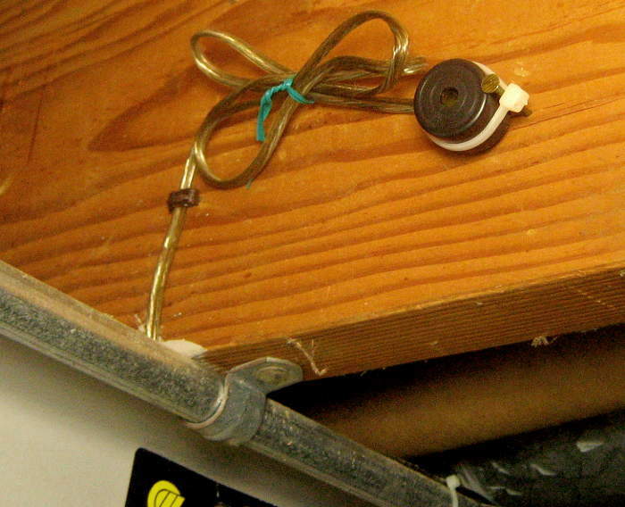
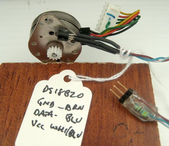
I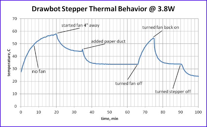 glued a good old DS18B20 temperature sensor to a spare stepper and monitored it with an Arduino (what else?). (Looks like the 1-wire pullup resistor was embedded in the header hot-melt.) While running full speed (but unloaded), I watched the temperature. I added a
 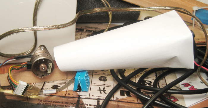 fan (looks like a 40mm) and a paper duct as about the most I could hope to cool it, and found the forced-air cooling was pretty effective.
From looking at stepper spec sheets, “real” steppers are often rated for 80C temp rise. From nominal 20C room temp, that would let it get to 100C and be in spec! I doubt this one is quite that robust, but with cooling, I could keep it well under 50C, so  that should be OK. I found some little 12V fans, and mounted them as close to the steppers as I could. This one had a DS18B20 glued on while I was doing initial testing with an Arduino and 1602 LCD
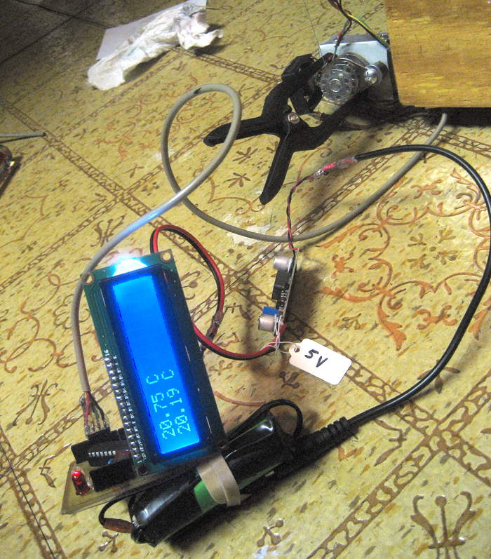
With the stepstick set for 400mA (Vref=0.64V) it stabilized at around 48C. With 300mA/0.48V, it did about the same. Bummer. After running a while (and stabilizing temp), after shut down to reduced current (not powered off) it cooled down to 30C. Immediately after it was done, powering off increased the temp a little before it started to go down, further evidence that the fans help a lot.
Now the two 12V fans I had in series across the 15V supply will need a series resistor. The motors are rated at 80mA, but measuring, we get:
6V 43mA
8V 50mA
10V 59mA
12V 66mA
14V 72mA
Shooting for say 50mA, I must drop 16V@50mA, or 320 ohms, but 0.8W! And maybe I shouldn’t cut current lower, since I need the cooling. So at 10V/motor, drop 12V@59mA or 203 ohms/0.7W. So I guess I’m looking for 270 ohms, 1W. Looks like a trip to Frys before I can fire it up. 🙁
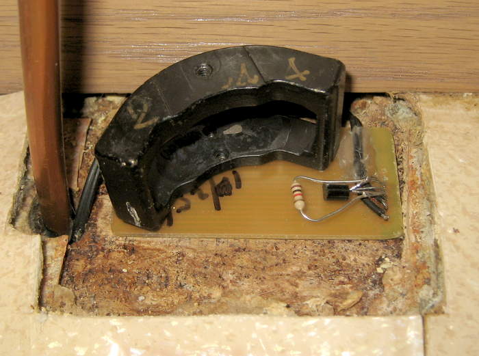
 The fans keep the motors under 50C while drawing, but they absolutely have to be running. I put the two fans in series, and also in series with them put a green LED (on the bottom side of the PCB, peering up thru a thinned bit of PCB) with a resistor in parallel with it (on top of PCB, not visible here) to carry part of the 50mA going thru the fans. That glowing part of the PCB is at once a 30V power LED and proof that there’s current going thru both fans. A valuable after-design hack to the PCB. <could use a better pic from the top>
PCBs
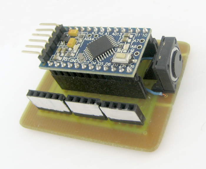 The original Duemilanove with jumpers hanging from its headers was replaced with a simple PCB ~9/15. It provided a mount for a Pro Mini, headers for the step/dir wires for the steppers and wire to the pen lift and a button to toggle the pen lift, and was a significant cosmetic improvement.
 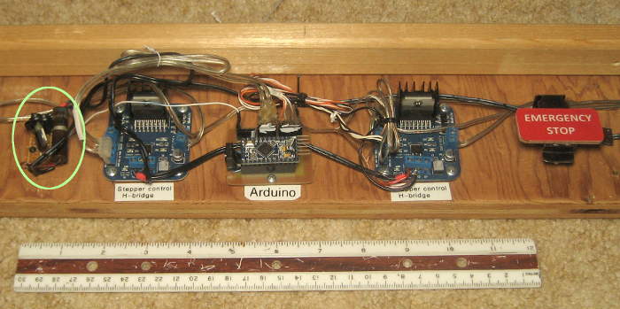 The power control / stepper cool-down circuit was on a separate bit of perfboard screwed down to the board on the bottom (green). That was ugly, but functional (and fully in the junkbox spirit!).
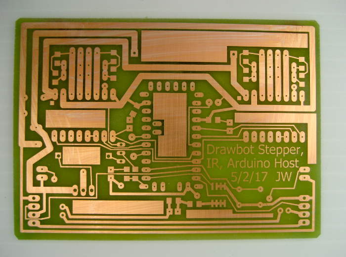 Driven by wanting to get rid of that power thing and to use the nice compact A4988 stepstick stepper controllers, freeing up the clunky H-bridges for their original project, a new PCB was born. By the time the board was made in May 2017, the drawbot was mature enough that most of its control needs were known and could be included on the new PCB, including IR LEDs for penlift comms.
BACKWARD STEPSTICKS
While I was installing the initial components on the new board, there was a big problem: The A4988 stepsticks were somehow backwards! (It was one of those interesting cases where something is so wildly wrong that it couldn’t really be that way. You have to re-evaluate all your assumptions, recheck all the details and figure out how this could possibly have happened – in addition to being slapped in the face with the fact that your project is completely broken. And then you have to figure out how to fix it!)
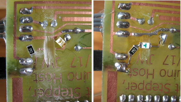
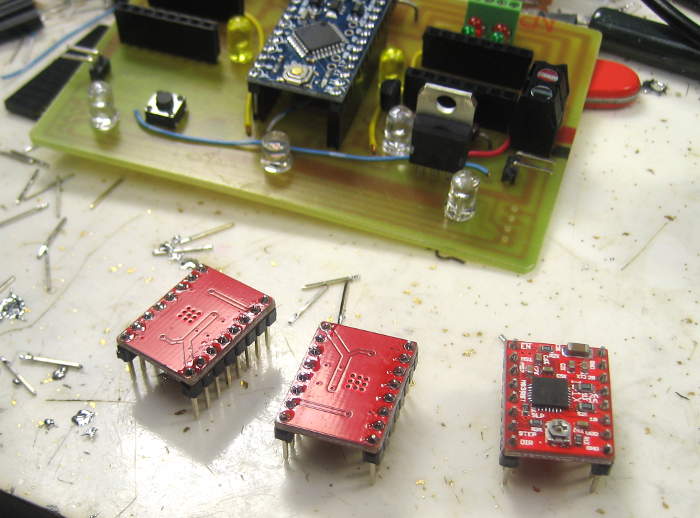 It turns out the Eagle footprint for the stepstick modules was backwards/mirrored in the reprap.lbr Eagle library. I could work around it by removing the pins from the modules and reinstalling them on the other side of the board. After I inverted the pins on the stepsticks, they seemed to be fine. (I marked a corner of each and each socket with white-out.) The current set pot is not accessible, and cooling may be an issue, but it worked.
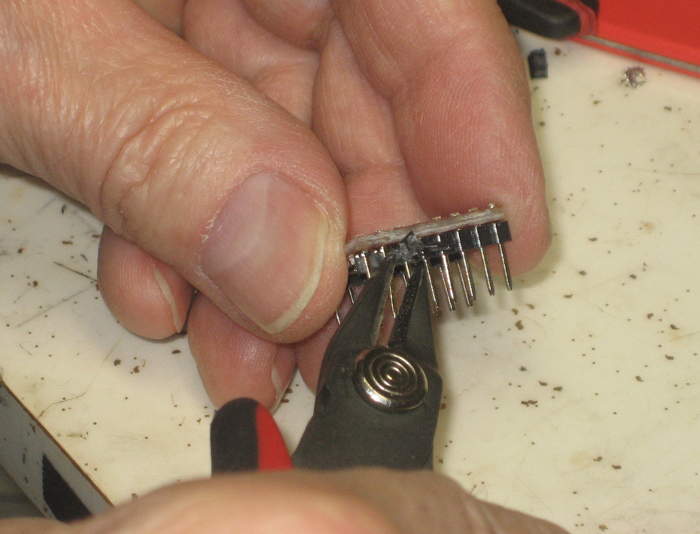 The pin inversion process started with cutting away the plastic band that held the pins together on
 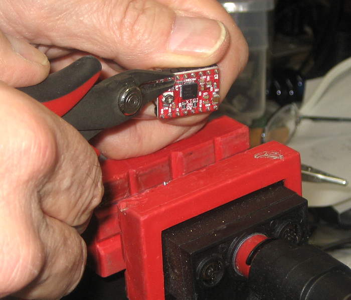 each side (as that was quicker than trying to pull it off). Clipping short ends of the pins off close to the board then made it easier to unsolder each one. A solder sucker cleared all the holes. Installing new pins on the new side was then easy.
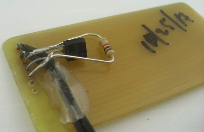
On the off chance I’d need to recall the procedure for inverting the pins, I wanted to document it. Of course when I started this unholy hack, my focus was on doing it without damaging anything, rather than documenting the process with these nice pictures. So I set up to take pictures as I prepped a third, spare stepstick. Murphy seized the opportunity, and as I was finishing up, I realized I had removed the pins from an already modified stepstick, not a new one. The picture above of pulling a pin after unsoldering it shows that too clearly. Rats.
The new PCB seems OK, tho it had a hairline open on the ground trace to the penlift button. I included a small loop of bare wire on ground to provide a convenient ground connection, and used it a couple of times during initial testing: Logic probe, neg side of temp power supply, ground for simulating button presses.
The red and green LEDs that show polarity for each coil are wildly different efficiencies. The reds have 8.2K series resistors, the greens 1K. I slipped up on installing the first set, swapping red and green. While I’d pictured red closest to the screw terminals, it really doesn’t matter, so I just did the second set the same wrong way. But when I tested them, the reds were WAY brighter than the greens, despite my efforts to balance them. That’s when I realized each color had the other’s resistors. Bummer. It was either hand unsolder/resolder the eight 1206 resistors (hmm – didn’t think of the hot air station!) or unsolder/resolder the LEDs. I chose the latter. I’d been double checking LEDs and polarity along the way, and when I finally got them in right, they all worked, and the brightness was quite well balanced.
Setting the reference voltage that determines the current limit on the stepsticks was a little scary at first, since the pot was now inaccessible under the board. But all you need to set the reference is Gnd and Vcc. Vref is from the slider on the pot, so a meter probe there 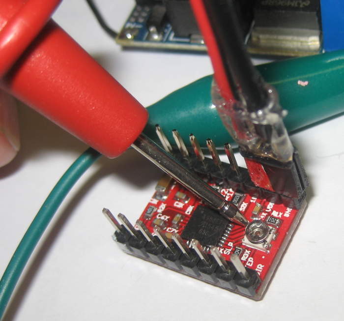 works fine. And in an uncharacteristically sloppy move on Murphy’s part, Vcc and Gnd are on adjacent 0.1″ spaced pins! Since my standard low voltage power connector is two adjacent 0.1″ pins, finding a nice color marked female with open leads was as simple as scrounging around on the bench a little. So while I do have to remove the stepstick module to change Vref, it’s pretty easy once it’s out.
Also note: Doing this with a bench supply was sort of OK, but since the real life reference voltage is a direct fraction of the 5V supply in place while it’s running, it may not be as accurate as you might hope. (Or be sure to match the bench supply accurately to your run-time source.)
All 3 buttons (2 rewind, on-board penlift toggle) work. They just have Atmel internal pullups, but there’s not a lot of noise, so that should be OK. IR comms works. I went thru the polarity of the various connections in the series loop of 6 IR LEDs to get them installed right. (Worked first try!) Having the pink LED in series with the IR LEDs to see when IR current flows was a very nice touch. Putting a resistor in parallel with it so it didn’t have to pass the 50mA pulses the IR LEDs saw was good.
Stepper, more upgrade 10/18
(writeup is work in progress) I got a couple of 37 oz-in NEMA 17 steppers from a group buy at W88, and ordered some brackets and 30T pulleys for the 5mm shafts. I planned to grind the teeth off, but didn’t, and they’re fine.
Shortened pulley stepper mounting “ears” to take advantage of stronger motors and still respect limiting cases top center (angle too shallow requires too much torque) and bottom corners (stepper must be outside so there’s a H component) by:
– lowering steppers to where I guessed they would still work for drawing at top center
– extrapolating string in that case, since any motion along that line wouldn’t matter for the top center limiting case
– drawing the line from bottom corner to old pulley position “because that worked”, and any motion along that line wouldn’t matter to the bottom corner limiting case
– chop/remount ears to be at intersection of those lines
Stepper drum axle alignment was off, so string piled up (on outside edge). Sighted with a square, also did stepper location v pen holder mount location, came to believe I needed the brackets to tile backward at ~3.2º. Held arm at correct angle with a measured block underneath, ground end on sandpaper taped to table. Looks good.
Redid electronics mount (no stepper mount stick) with screws that fit into slots in back board for slide-on, no tool assembly. Nice. Cabled steppers with phone station wire, 2×4 0.1″ headers for twice current capacity, and mounted females at corners of electronics board. Built/cabled a dedicated USB-TTL serial adapter and mounted it. Found solder joints under 24V screw terms were bad; fixed. Overall pretty good.
Had to hack Arduino code (still Dan Royer’s, modified) for steps/turn, microsteps, new ver # (JW4). Got reacquianted with my custom D codes (D7, D3, D55) and of course G54 to locate artwork where I want on the paper.
After a few initial stumbles, it seems to be working very. Even with the 33V supply, the motors don’t get very hot (so far!). I’m leaving the grbl update for later. This works, and has enough brute strength to not really need acceleration control.
Plan is to show it at Norther Illinois Mini Maker Faire Oct 27. I’m working on artwork now – rather than desperate hardware work. Yay!
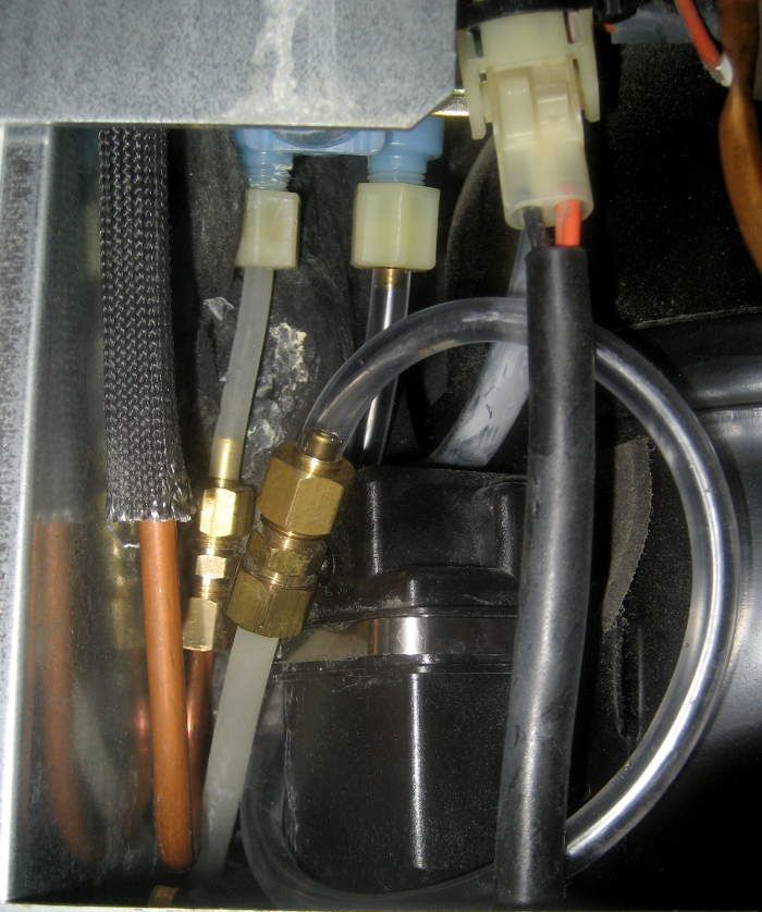
UV cure resin to lock tie-down loops
 I made some nice loops out of braided nylon rope to let one bungee cord fit nicely to hold the “long stuff” together.
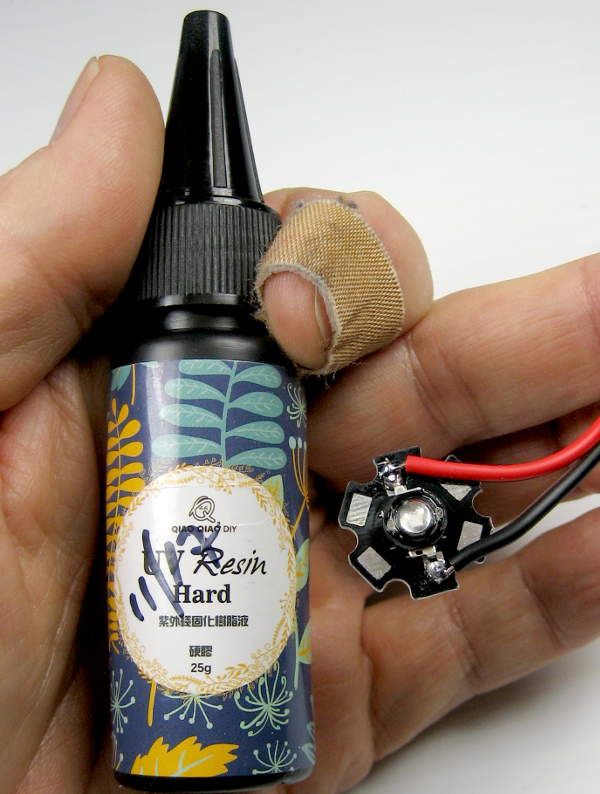 I was afraid the knots might come loose, so I slobbered some cheap Chinese UV-cure resin on them. It’s half an experiment to see if that’s a good way to hold a knot in place. While the old 18650/UV LED flashlight seems to work OK, I used a new 3W 365nm LED.
 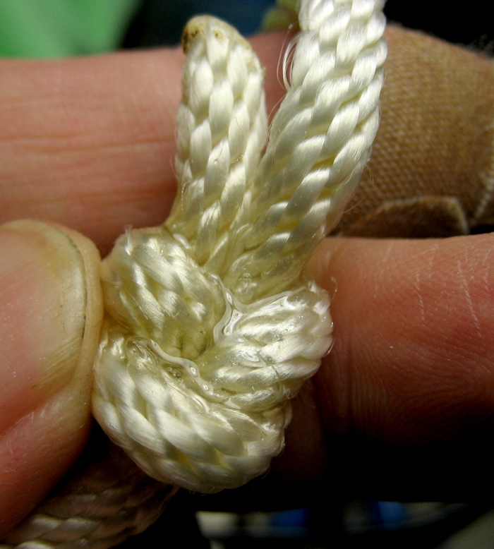 That worked maybe a little better. Interestingly, the new stuff doesn’t fluoresce under UV like the Bondic resin does, so the clear resin barely shows up in the pic. Don’t know if Bondic puts fluorescent dye in for some bling or practical reason, or whether it’s intrinsic in their resin.
Resume
 One of the first things I’d like to draw and hang up at a maker event is a resume for the drawbot. (Hasn’t happened yet.) A picture of the applicant is customary on a resume, and the (planned) one started with a line picture of the drawbot. But as soon as I first
  saw it (thanks, Rachel!) I wanted to use makerblock‘s cute drawing robot instead of line drawing of mine. I wrote to Jay and he’s graciously allowed me to use it (with attribution). Thanks, Jay!
Caricatures
I think it would be really cool to have a resident artist who could create line art caricatures of people by tweaking software generated cartoons from live photos – and have the bot draw them. That could almost be a money maker somewhere. Has absolutely nothing to do with the drawbot, but since that’s what’s holding the pen, I suspect people will eat it up. Posted that to W88 list, got ZERO replies. Some day.
Tool chain
ARTWORK NOTES
I’ve come a long way with Inkscape. Most recently, I found reference to a mirroring feature in Live Paths I thought would be useful, but it’s only available in 0.92, and I was running 0.91. Of course I upgraded. 🙂 But Create Tiled Clones and Path Effects provide some very powerful effects. I’m strongly considering doing a class on basics at the space. There are so many tricks like the align/distribute thing, grids, guides, snapping, sizing by entering values – I think I could do a real service to anyone trying to learn about the tool. Great – another project. 🙂
Path->Linked offset creates a _new_ path and lets you inset/outset it. Watch out for jaggies if your original path has anything non-smooth. It rounds sharp corners inside or outside, depending. Useful for creating fill sometimes.
Eggbot Contributed Hatch Fill extension is pretty good, but you have to futz to get what it makes to be part of your path. Path effects->Hatch(Rough) is cool, but converts the existing path to squiggle. If you want outline path, dup it first. Click node tool to see handles to change spacing! Note that it generates multiple hatch paths if there are multiple overlapping fill areas.
I finally got the Gcode Extensions-> Path to Gcode pretty much working, but it required many steps of editing the gcode it produced to not run afoul of Dan’s implementations (Java and Arduino). So I dug into the python scripts that implement it, and after many hack to that, I have a gcodetools.py that generates code that will run directly on the drawbot – a huge time saver. I cut lots of corners – only works for Path to Gcode (not Engraving, Graffiti, Lathe); no tool change support; no comments; removed a leg that (only) occasionally generated a Radius-format arc command; probably more.
For that to work most seamlessly, there are modifications to the default orientation points needed. In Orientation Points, set Z-Surface to 50.9, Z-Depth to 50. In Path to Gcode Preferences, be sure to put a suitable file name in, and set Z safe height to 90. I think those (along with the hacked gcodetools.py) are sufficient to generate working gcode first try.
So I guess steps are:
– Create artwork – apparently must be on a layer, but I don’t understand that requirement. Some times it complains, other not.
– A reasonable size to get 9 images on the paper is 250x250mm.
– If you want it centered on 0,0, make a very small circle and center it (X and Y) on your artwork with align/dist tool. Group it with them (probably multi-select works) and drag it so the small circle is centered on the bottom left corner of the document outline. Then ungroup and delete the extra circle. Don’t do Document Properties->Resize Document to Selected! select the whole target artwork and drag it so it’s centered on the lower left corner of the document. Fine tune by making sure both the top arrows (for vert resize) and the right edge arrows (for horiz resize) are centered on the edges of the document outline.
– Highlight the paths you want to generate gcode for. (For multiple colors, do each as a separate gcode file, separate name.) Must be _paths_ – might need Path->Object to Path).
– Do Extensions->Gcode Tools -> Orientation points. Set Z surface 50.9, Z depth 50. Close that dialog.
– With inkscape 0.92, double click the orientation points object, then select the right hand one. Be sure to get the arrow, not just the text! Assuming millimeters, set X=100 (prob was 354 or so) in the boxes at the top. It will overlap and be ugly, but it will work. UPDATE: I just tried it 10/3/17 and the orientation point was at 354,0 but said 100,0! Had to change it to 354,0 and then it worked. Huh? Also retried with 0.92.3 10/10/18 and also had to change to 354,0.
– Do Extensions->Gcode Tools -> Path to Gcode. Set nice file name, path. Set Z safe height to 90, units to mm (though I think that doesn’t matter any more). Probably check Sort paths to reduse [sic] rapids. Be sure your desired paths are still selected. Select Path to Gcode tab or it will complain. Click Apply.
– After some popups including setting a default tool, it should leave a representation of the gcode path (red for lines, green/blue for arcs) on top of your artwork. Select it with object tool, [drag it away,] and delete it.
– Check out your new gcode! Only F param is on second line. It’s hard coded in gcodetools.py; change it if needed.
– New gcode plugin: Laser – maybe unicorn?
There are also artwork notes in drawbot\artwork\_ReadmeArtworkTechniques.txt.
I could probably pick up a bunch of stuff from a session of youtube searches on “inkscape tips”.
Sound bites
A possible way to add interactivity to the drawbot would be to plot Lissajous-like figures from a mic audio clip from a visitor. She talks, sings, makes whatever noises into a laptop app that creates some sort of Lissajous figure, adjusting/redoing ’til she likes it, and types in her name. I need: an app to generate an interesting path from a few seconds of audio; and an app to generate gcode from that path. The kid gets to pick a pen color, and the drawbot plots it (with name). I bet there’d be a line to play. Afterwards, cut the big page and give each kid her “work of art”. Maybe version 17 would support multiple sub-paths/colors.
Vine and flower
Assume say 9 spots on a sheet and fill the first 7 spots with whatever drawings. Create a green vine with leaves that weaves around the drawings, starting growing out of the newly drawn Groot down in one corner, ending in a flower in say top left ninth. Changing pen color for the flower would be a great finish.
User manual
USER MANUAL
OK, let’s start to collect stuff. Not a bad time, since I haven’t used it for a while.
Overview list of topics:
– setup – mechanical: pieces needed, assembly, on a table, on floor, tools
– setup – software: software needed: makelangelo, gcode viewer, inkscape,other?; organizing gcode files; software dimension inits
– setup – electrical: power; estop switch; serial cable; LED indications; penholder connections, penholder power switch; charging
– operation:
– setting origin: G20, D7 sets current position to be 0,0.
STARTING OUT:
Connect serial cable and make sure Windows sees it. Fire up Makelangelo java app. Grab bottom edge and open up terminal window at bottom (but don’t cover HALT – you may need it!). Click CONNECT, choose serial port. Should get orange hello from Arduino in terminal window.
SETTINGS: We’re a Makelanelo2+. Machine width (with new NEMA steppers) 1600mm; height 2060 mm; pulley diam: 22.8 cm. Paper is really about 900×900, but I seldom tell it it’s that big. Setting size to 280×280 give good visualization of the typical 1/9 of paper artwork pieces (if no G2/G3 arcs). Margin is only used by Makelangelo’s Generate Artwork stuff. Pen Max speed and Draw speed are in steps/sec (not /min). Max might limit max speed, but maybe not. Draw speed is if you don’t ever give it an F command before doing a G0 or G1 (or G2 or 3). Pen angle is sort of hard coded at 90=up, 50=down. Lift delay of 60 seems to work OK.
ADVANCED STARTUP: Right after Arduino init, the origin is set to a point high off the board. Never try to do anything (like jogging!) until you’ve told it somewhere more reasonable as the origin! The “real” origin is the lower LED – right in the middle of the paper. The 36″ paper is about +/- 450 mm from the center to edges. Using that, you can make a rough guess at the absolute coords of where ever the pen happens to be as you’re setting up. For example, if it’s in the middle of the lower right quadrant, that’s about X200 Y-200. You can always enter a G92 with those values and things will be close enough for the jog controls to work (assuming you’re in G54 and G21!). Once jog controls work, you can get to where you need to go.
Connect 33V stepper power brick. It might be possible to upset it (requiring power cycle?) if you touch wrong ends of connector even briefly. Put little finger pad up under ESTOP switch and make sure it’s it its uppermost position. (Either middle or bottom is OFF.) Green LED should come on and should hear fans. Blue LED should be on.
Use buttons at outboard IR LEDs to take up some slack on strings so penholder is about in middle of paper. In data entry line at bottom of terminal, enter D7 (=G92 X0 Y0). Use jog controls to move pen tip to high LED behind paper. Enter D8 (=G92 X-20 Y330). Machine now knows where it is and geometry should be good.
SETTING UP FOR A DRAWING:
Use jog controls to move to origin of where you want a drawing. Need to know if this drawing is centered on 0,0 or orig is at bottom left corner. Enter D55 to set G55 coord system and set its origin at current loc. At this point the coord system should be good to go.
Click Open File, click bottom (NGC) file type selector, navigate to file, and accept. You should get a representation of the file on the visualizer. If it has arcs, there will be scribbles – just ignore them.
Turn IR receiver on penholder on with small slide switch (having made sure Li-ion cell is charged). Up is off – sorry. Should get a red-green cycle of penlift and LEDs, ending with pen up (green). Insert pen so tip is ~1/16″ above paper and tighten clamp screw. (I should put a stop in for this!) At this point, you should be able to click Start and get your plot! If it’s multi-color, choose the next file, change pen, and do it again.
WARNING! When you’re in G55 coord system, the jog controls DON’T WORK RIGHT! DON’T USE THEM! G91 doesn’t work, so don’t even try to jog by entering commands that way. Unless you’re CERTAIN what units the drawing left, do a G20|G21 before trying to jog with G0 commands. Must give absolute destination in local coord system.
HINT: After you set the local origin, you might want to drop the pen tip and bring it back up (2 presses of the Toggle Penlift button by the green LED so you know where it started. Might be helpful if you have to restart, or just to check after a G0 X0 Y0 after the plot for missed steps.
TO GET BACK TO NORMAL: Enter G54 to go back to the standard coord system. That and a G21 will make the jog controls work as expected again. It’s EASY to forget you’re in G55 or in inches! If you do, the pen holder will launch off for parts unknown, requiring a quick ESTOP and starting all over. Maybe I should add another D-code to do both.
CLEVER PEN HOLDER HANGER: If the penholder is some above Y0, you can put the hanger in place and kill power (ESTOP) and the holder will gracefully start to fall and be caught by the hook. Works really well once you see it. Hang the hanger on the top edge way over to one side when not in use.
SPECIAL D COMMAND LIST:
– D3: go to local 0,0 (G0 X0 Y0)
– D7: set current location as origin (G92 X0 Y0) Only do this as a crude starting position or when the pen is right over the lower LED hole if you want the machine to work right.
– D8: set current loc as where the upper LED is (G92 X-20 Y330). Normally only used when the pen is actually right at the LED.
– D9: go to high LED loc (G0 X-20 Y330)
– D55: switch to G55 coord system AND set 0,0 as current loc as 0,0 in G55. NOTE THIS IS D55, not G55! G55 won’t set origin!
– G45-G59: set the work coord system. This is reflected as “tool N” where N is (G5x param-54)
– M114: print current loc, tool, offset etc
CHANGING PAPER: When one sheet is full and it’s time for another:
– Move the pen holder up out of the way by being sure you’re in G54, then manually entering G0 X0 Y700. Guide it over the top edge. It dangles, but is stable.
– To remove the old paper, FIRST remove the tape from the bottom corners/edge. THEN run the paper cutter across the top to slice the paper off.
– Pull new paper (which has flipped back over the top, but is easily reached) down over the top edge of the backboard to help uncurl it. I leave the bottom edge 4-5″ above the controller board.
– Tape at least the bottom corners. I usually put a piece at bottom center, too. I haven’t put anything on the vertical edges since the new ring penholder.
– Type G0 X0 Y300, but don’t hit return until you’re in position to guide the penholder by hand back over the top edge. You can let go as soon as the pen (lift) is on the drawing surface.
– Tape drawing to refrigerator (or…).
LEDs:
– The yellow LEDs flanking the Arduino are last direction.
– The green LED in lower left is in series with fans. No fans, no LED. Assuming fans are OK, it’s basically a 33V power indicator.
– The pink LED front center blinks when an IR command is sent to the penholder. It’s in series with the IR LEDs, so if it blinks, the IR LEDs flashed.
– The blue LED near the power transistor is on when power supply is in idle mode, off when steppers are fully powered. When blue is on, 33V power goes thru the 65 ohm resistor at the back, so steppers have enough current to keep the penholder in place (and click when you force turn them), but let the steppers cool down. If you hit ESTOP, when the blue LED is on, the steppers aren’t going anywhere any more.
– The red and green LEDs by the screw terminal strips to the motors are current presence/polarity on each of the motor’s 2 phases. Not useful, but enjoyable.
BUTTONS:
– The button near the green LED toggles the pen lift. You can press it (twice) to make a dot at the current position (presumably an origin). Might be useful to reduce damage if a pen lift command is lost and it’s scribbling when it shouldn’t be.
– The buttons on the small PCB with the outboard IR LEDs are motor windups. (There is no powered unwind.) Useful after an ESTOP to get the penholder back somewhere near the middle, and during teardown to wind up the string for transport. Needs 33V power and 5V to Arduino, but doesn’t need anybody talking to the Arduino.
NOTE that even if 33V is connected (and ESTOP is up/ON) the motors don’t get any current until there’s 5V to the stepsticks (which means to the Arduino as well).
FILE MANAGEMENT:
Since the java app defaults to opening My Documents, consider putting your artwork one dir under that, or somewhere else you can get to it quickly. Maybe have all the known good artwork in that top folder, and a sub folder for test stuff, or imperfect stuff, or older versions. When people are waiting for you to make it draw something, you don’t want to have to dig thru directory structures.