
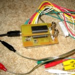
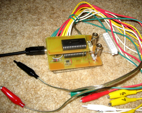
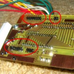
The battery discharge tester hardware is essentially complete. You can see the 15 clip leads that go to the cell connections plus the red/black heavy clips that go to the very top and bottom to carry the discharge current.
-
- Double-decker discharger
-
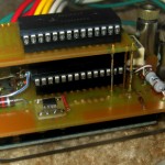
- Discharger closeup
-
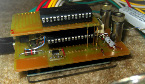
- Pins for Arduino
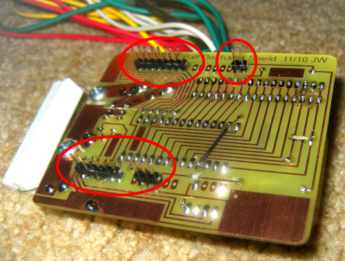
The daughterboard with the second 16:1 mux chip is the top layer. There really is an Arduino underneath. You can see the pins that make it a “shield” circled on the bottom view. The Eagle library from SparkFun for Arduino shields put those pins exactly where they needed to be. There were an embarassment of hacks to the board.
The bad news is that it doesn’t work. This application of the analog switch is kind of strange – using the chip to connect different cells to ground at different times. I think it’s all within spec, but the first time I started to hook all the leads up the chips got very hot. Now it doesn’t seem to work at all.
I have one new chip. One possibility is to re-hack the board to use a single chip, with one end of the whole battery always connected to ground (instead of using one chip to connect ground and the other to connect the analog input to the cell of interest). I get an order of magnitude less voltage resolution, but it’s probably (just barely) enough to do the job. But if there’s something I missed about the chip, that might not work, either.
I’m not sure what my next step will be.
Jim, I ran across your project after researching the DG406/7 Mux chip. I am interested in how you interfaced your Arduino into it. I am working on a similar project that scans over a pack of batteries and samples the voltage, and collects the data for a trend. My batteries are 12v each 6 total. A little worried like you about getting lines crossed and shorting the pack. Drop me a line, would love to chat about it.